Opel Frontera UE. Manual - part 103
 

  Index      Opel     Opel Frontera UE - service repair manual 1999-2001 year


Search            


Content   ..  101  102  103  104   ..


Opel Frontera UE. Manual - part 103


4C–46

DRIVE SHAFT SYSTEM

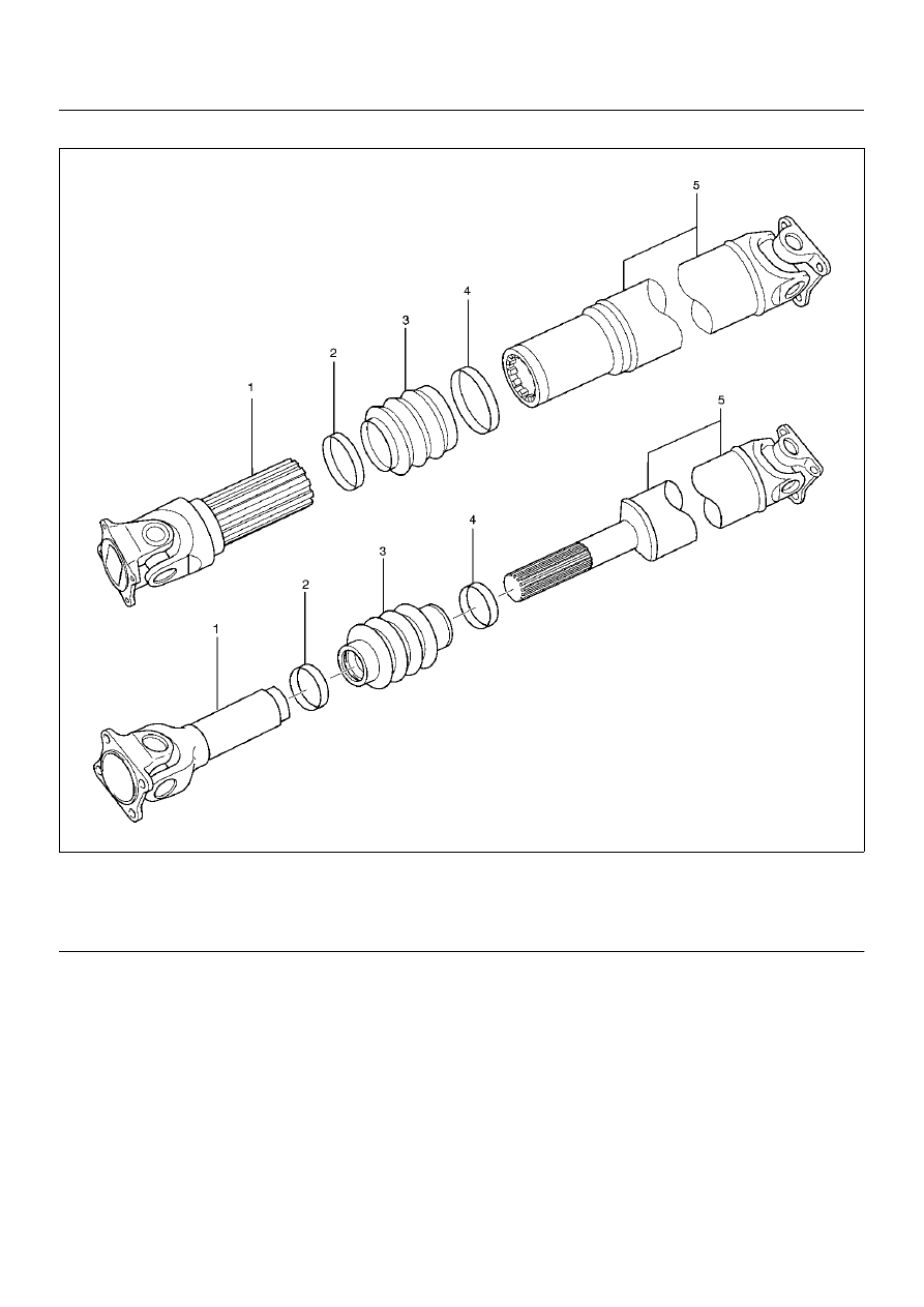
Slip Joint Reassembly

401RX004

Legend

EndOFCallout

1. Apply grease evenly to both the female and male 

splines.

2. Apply a small amount of grease by finger to the 

outer lips of the boot.

3. Slide the boot (smaller diameter side) onto the 

spline yoke shaft being careful not to damage the 
spline coating or boot.

4. Insert the spline yoke shaft spline into the tube 

assembly being careful to maintain proper phasing.  
The spider holes should be in line and as per 
originally marked prior to disassembly.

5. Position boot onto tube and yoke shaft in final 

position.

6. Attach boot clamps and secure using pliers.

7. Be sure clamp is properly seated and secure.

CAUTION:  Use new clamp which is the same parts 
as original. Do not use other clamp to avoid bad 
balancing of shaft or the grease leakage.

(1) Spline Yoke and Universal Joint Assembly
(2) Clamp
(3) Boot

(4) Clamp
(5) Tube and Universal Joint Assembly

DRIVE SHAFT SYSTEM

4C–47

Main Data and Specifications

General Specifications

Torque Specifications

E04RX013

4WD Model

Engine

X22SE

6VD1 (M/T)

6VD1 (A/T)

Length (between two spiders center)

989.0mm (38.94in)

1212.5mm (47.73in)

1043.0mm (41.06in)

Universal joint type

Cardan type

TRANSFER CASE

4D–1

FRONTERA

DRIVELINE/AXLE

TRANSFER CASE

CONTENTS

Service Precaution

4D–1

. . . . . . . . . . . . . . . . . . . . . . 

General Description

4D–2

. . . . . . . . . . . . . . . . . . . . . 

Transfer Rear Oil Seal

4D–4

. . . . . . . . . . . . . . . . . . . 

Transfer Rear Oil Seal and
 Associated Parts

4D–4

. . . . . . . . . . . . . . . . . . . . . . 

Removal

4D–4

. . . . . . . . . . . . . . . . . . . . . . . . . . . . . 

Installation

4D–4

. . . . . . . . . . . . . . . . . . . . . . . . . . . . 

Transfer Case Assembly (A/T)

4D–6

. . . . . . . . . . . . 

Transfer Case Assembly (A/T) and
 Associated Parts

4D–6

. . . . . . . . . . . . . . . . . . . . . . 

Removal

4D–7

. . . . . . . . . . . . . . . . . . . . . . . . . . . . . 

Installation

4D–8

. . . . . . . . . . . . . . . . . . . . . . . . . . . . 

Transfer Rear Case Assembly (A/T)

4D–11

. . . . . . . 

Transfer Rear Case Assembly (A/T) and
 Associated Parts

4D–11

. . . . . . . . . . . . . . . . . . . . . . 

Removal

4D–11

. . . . . . . . . . . . . . . . . . . . . . . . . . . . . 

Installation

4D–13

. . . . . . . . . . . . . . . . . . . . . . . . . . . . 

Transfer Rear Cover Assembly

4D–16

. . . . . . . . . . 

Disassembly

4D–16

. . . . . . . . . . . . . . . . . . . . . . . . . . 

Inspection and Repair

4D–17

. . . . . . . . . . . . . . . . . . 

Reassembly

4D–17

. . . . . . . . . . . . . . . . . . . . . . . . . . 

Detent, Shift Arm, and Interlock Pin
 (Transfer Case Assembly)

4D–19

. . . . . . . . . . . . . . . 

Disassembled View

4D–19

. . . . . . . . . . . . . . . . . . . . 

Disassembly

4D–20

. . . . . . . . . . . . . . . . . . . . . . . . . . 

Inspection and Repair

4D–21

. . . . . . . . . . . . . . . . . . 

Reassembly

4D–21

. . . . . . . . . . . . . . . . . . . . . . . . . . 

Transfer Case Assembly

4D–23

. . . . . . . . . . . . . . . . . 

Disassembled View

4D–23

. . . . . . . . . . . . . . . . . . . . 

Disassembly

4D–24

. . . . . . . . . . . . . . . . . . . . . . . . . . 

Inspection and Repair

4D–27

. . . . . . . . . . . . . . . . . . 

Reassembly

4D–30

. . . . . . . . . . . . . . . . . . . . . . . . . . 

Main Data and Specifications

4D–37

. . . . . . . . . . . . . 

Special Tools

4D–40

. . . . . . . . . . . . . . . . . . . . . . . . . . . 

Service Precaution

WARNING: THIS VEHICLE HAS A SUPPLEMENTAL
RESTRAINT SYSTEM (SRS). REFER TO THE SRS
COMPONENT AND WIRING LOCATION VIEW IN
ORDER TO DETERMINE WHETHER YOU ARE
PERFORMING SERVICE ON OR NEAR THE SRS
COMPONENTS OR THE SRS WIRING. WHEN YOU
ARE PERFORMING SERVICE ON OR NEAR THE SRS
COMPONENTS OR THE SRS WIRING, REFER TO
THE SRS SERVICE INFORMATION. FAILURE TO
FOLLOW WARNINGS COULD RESULT IN POSSIBLE
AIR BAG DEPLOYMENT, PERSONAL INJURY, OR
OTHERWISE UNNEEDED SRS SYSTEM REPAIRS.

CAUTION: Always use the correct fastener in the
proper location. When you replace a fastener, use
ONLY the exact part number for that application.
ISUZU will call out those fasteners that require a
replacement after removal. ISUZU will also call out
the fasteners that require thread lockers or thread
sealant. UNLESS OTHERWISE SPECIFIED, do not
use supplemental coatings (Paints, greases, or other
corrosion inhibitors) on threaded fasteners or
fastener joint interfaces. Generally, such coatings
adversely affect the fastener torque and the joint
clamping force, and may damage the fastener. When
you install fasteners, use the correct tightening
sequence and specifications. Following these
instructions can help you avoid damage to parts and
systems.

SECTION

4D–2

TRANSFER CASE

General Description

Transfer Case (for Manual Transmission)

A07RX005


Content   ..  101  102  103  104   ..