Nissan Frontier (2023 year). Manual in english - page 11


  Index      Manuals     Nissan Frontier (2023 year). Manual in english


Search            copyright infringement  


Content      ..     9      10      11      12     ..


Nissan Frontier (2023 year). Manual in english - page 11


To use the outlets for devices that require
up to 120v power, the vehicle must be run-
ning and the power inverter switch must
be on.

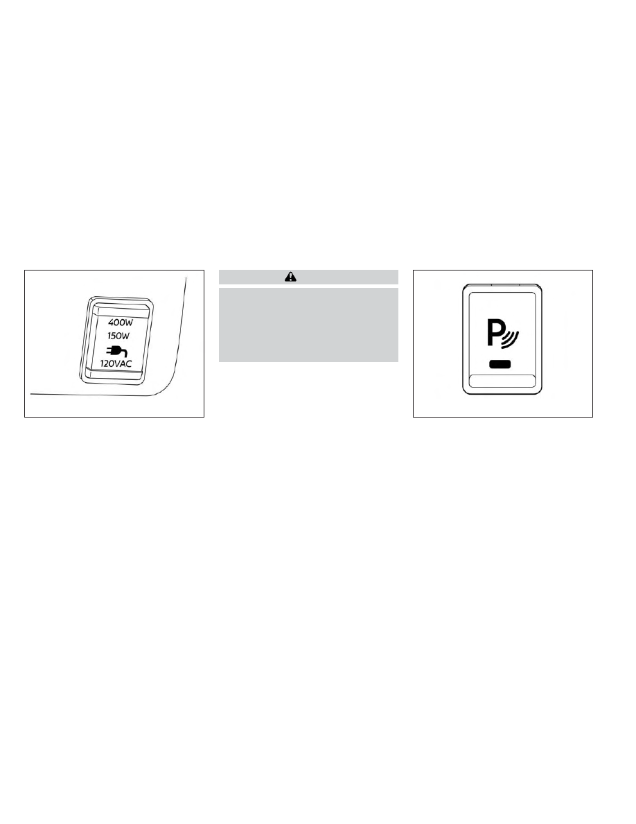
When the vehicle is in the P (Park) position,
the 400W and the 150W will automatically
illuminate. When the vehicle is out of the P
(Park) position, only 150W will illuminate.

For additional information, see “120v out-
lets” (P. 2-61) regarding using devices that
require the power inverter switch to be
activated.

CAUTION

Use power outlets with the engine
running to avoid discharging the ve-
hicle battery.

Do not use double adapters or more
than one electrical accessory, doing
so could significantly drain the bat-
tery of your vehicle.

The Parking Aids system switch on the in-
strument panel allows the driver to turn
the following systems (if so equipped) on
and off. To turn the systems on and off, the
ignition switch must be in the ON position.
• Rear Sonar System (RSS) (if so equipped)
• Moving Object Detection (MOD) (if so

equipped)

• Rear Automatic Braking (RAB) (if so

equipped)

• Rear Cross Traffic Alert (RCTA) (if so

equipped)

LIC4847

LIC3596

POWER INVERTER SWITCH (if so
equipped)

PARKING AIDS SYSTEM SWITCH (if so
equipped)

2-56

Instruments and controls

-------------------------------------------------------------------------------------------------------------------------------------------------------------

The indicator light on the switch will illumi-
nate when the systems are turned on.

If the indicator light flashes when the RSS,
MOD, RAB, or RCTA systems are not turned
off, it may indicate a malfunction in one or
more of these systems (if so equipped).

The RSS, MOD, RAB, or RCTA systems will be
turned on automatically under the follow-
ing conditions:
• When the ignition switch is switched from

the OFF position to the ON position.

• When the shift lever is shifted into the R

(Reverse) position.

The automatic turning on function can be
turned on and off for these systems in the
vehicle information display. For additional
information, see “Settings” (P. 2-26).

For additional information, see “Rear Sonar
System (RSS)” (P. 5-124), ”Rear Automatic
Braking (RAB)” (P. 5-76), “Rear Cross Traffic
Alert (RCTA)” (P. 5-42), or “Moving Object De-
tection (MOD)” (P. 4-24).

Tow mode should be used when pulling a
heavy trailer or hauling a heavy load. Driv-
ing the vehicle in the tow mode with no
trailer/load or light trailer/light load will
not cause any damage. However, fuel
economy

may

be

reduced,

and

the

transmission/engine driving characteris-
tics may feel unusual.

Push the tow mode switch to activate tow
mode. The TOW mode ON indicator light
illuminates when tow mode is selected.
Push the tow mode switch again to turn
tow mode off.

Tow mode is automatically canceled when
the ignition switch is placed in the OFF
position.

For additional information, see “Towing a
trailer” (P. 10-27).

LIC4845

TOW MODE SWITCH (if so equipped)

Instruments and controls

2-57

-------------------------------------------------------------------------------------------------------------------------------------------------------------

EMERGENCY SUPPORT

NissanConnect® Services provide various
services to support dealing with emergen-
cies of the subscribed vehicle and the
driver.

For example, in case of an illness or serious
injury, you can seek support by pressing the
in-vehicle Emergency Call (SOS) button and
connecting to the NissanConnect® Services
Response Center. The NissanConnect® Ser-
vices Response Center can specify the loca-
tion of the vehicle via GPS, and the informa-
tion will be sent to the police or other
agencies as needed.

For information about other NissanConnect®
Services emergency support related ser-
vices, contact the NissanConnect® Cus-
tomer Support line at 1–855–426–6628 or
refer to the NissanConnect® Services web-
site www.nissanusa.com/connect (for U.S.)
or www.nissan.ca/nissanconnect (English) /
www.nissan.ca/nissanconnect/fr

(French)

(for Canada).

WARNING

Please note that the Automatic Colli-
sion Notification service and Emer-
gency Call function cannot be used in
the following conditions:

Emergency functions and services
will not be available without a paid
subscription

to

NissanConnect®

Services.

The NissanConnect® Services net-
work system is disabled.

The vehicle moves outside the
service

area

where

the

TCU

(Telematics Control Unit) is con-
nected to the system.

The vehicle is outside the area
where the cellular network service
is receivable.

The vehicle is in a location with
poor signal reception such as tun-
nels,

underground

parking

ga-

rages, behind buildings or in moun-
tainous areas.

The line is busy.

The TCU (Telematics Control Unit)
or other systems of your vehicle
are not working properly.

It may not be possible to make an
emergency call depending on the
severity of a collision and/or
emergency.

Park the vehicle in a safe location and
set the parking brake before operat-
ing the Emergency Call (SOS) button.

Only use this service in case of an
emergency. There may be a penalty
for inappropriate use of the service.

Radio waves could adversely affect
electric medical equipment. Indi-
viduals who use a pacemaker should
contact the device manufacturer re-
garding any possible effects before
using the system.

The TCU (Telematics Control Unit) an-
tenna is installed inside the upper
central part of the instrument panel.
An occupant should not get any
closer to the antenna than specified
by the pacemaker manufacturer. The
radio waves from the TCU antenna
may adversely affect the operation
of the pacemaker while using the
NissanConnect® Services.

EMERGENCY CALL (SOS) BUTTON
(if so equipped)

2-58

Instruments and controls

-------------------------------------------------------------------------------------------------------------------------------------------------------------

Making an emergency call

The Emergency Call (SOS) button is located
near the map light.

1. Press the Emergency Call (SOS) button

to make an emergency call.

2. When the line is connected, speak to the

Response Specialist.

If you want to cancel the emergency call,
press and hold the Emergency Call (SOS)
button for a few seconds.

NOTE:

After the Emergency Call (SOS) button
is pressed, it may take some time until
the system initiates connection, de-
pending on the technical environment
and whether the TCU (Telematics Con-
trol Unit) is being used by the other
services.

An indicator light on the Emergency
call (SOS) button shows the readiness
of the emergency support system. If
the indicator light is not illuminated,
pressing the Emergency Call (SOS) but-
ton does not connect your vehicle to
the Response Specialist. The indicator
light blinks while connected to the
NissanConnect®

Services

Response

Center.

Even when the indicator light is illumi-
nated, connection to the NissanConnect®
Services Response Center may not be
possible. If this occurs in an emergency
situation, contact the authorities by
other means.

To avoid disconnecting the line, keep the
engine running during an emergency
call, if it is safe to do so.

The Rear Door Alert system functions un-
der certain conditions to indicate there
may be an object or passenger in the rear
seat(s). Check the seat(s) before exiting the
vehicle.

The Rear Door Alert system is initially dis-
abled. The driver can enable the system
using the vehicle information display. For
additional information, see “Vehicle infor-
mation display warnings and indicators”
(P. 2-33).

When the system is enabled:
• The system is activated when a rear door

is opened and closed within 10 minutes of
the vehicle being driven. When the driver’
door is closed and the system is acti-
vated, a visual message appears in the
vehicle information display. For additional
information, see “Rear Door Alert is acti-
vated” (P. 2-35).

• If a rear door is opened and closed but

the vehicle is not driven within approxi-
mately 10 minutes, the system will not be
activated. A rear door must be opened
and closed and the car driven within 10
minutes for the system to activate.

LIC3376

REAR DOOR ALERT

Instruments and controls

2-59

-------------------------------------------------------------------------------------------------------------------------------------------------------------

When the Rear Door Alert system is acti-
vated and a driver exits the vehicle after
arriving at a destination:
• When the driver puts the vehicle in the P

(Park) position, a message appears in the
vehicle information display for a driver
to “Dismiss Message” or “Disable Alert” if
desired.

• With the system enabled, when the driver

exits the vehicle, an audible alert (horn
sound) will occur unless a rear door is
opened and closed within a short time to
deactivate the alert.

• If the doors are locked before the alert is

deactivated by opening a rear door, the
horn will sound.

• If the audible horn alert occurs, a mes-

sage will also appear in the vehicle infor-
mation display that states, “Check Rear
Seat for All Articles”.

WARNING

• If the driver selects “Disable Alert”, no
audible alert will be provided regard-
less of rear door open/close status.

• There may be times when there is an
object or passenger in the rear seat(s)
but the audible alert does not sound.
For example, this may occur if rear seat
passengers enter or exit the vehicle
during a trip.

• The system does not directly detect
objects or passengers in the rear
seat(s). Instead, it can detect when a
rear door is opened and closed, indicat-
ing that there may be something in the
rear seat(s).

NOTE:

There may be times when the horn
sounds but there are no objects or pas-
sengers in the rear seat(s).

For additional information, see “Rear Door
Alert is activated” (P. 2-35).

12V OUTLETS

The power outlets are for powering electrical
accessories such as cellular telephones.

The power outlet located on the instru-
ment panel is powered only when the igni-
tion switch is placed in the ACC or ON
position.

Open the cap to use a power outlet.

CAUTION

The outlet and plug may be hot dur-
ing or immediately after use.

LIC4831

Instrument panel

POWER OUTLETS

2-60

Instruments and controls

-------------------------------------------------------------------------------------------------------------------------------------------------------------

Only certain power outlets are de-
signed for use with a cigarette lighter
unit. Do not use any other power out-
let for an accessory lighter. It is rec-
ommended that you visit a NISSAN
dealer for additional information.

Do not use with accessories that ex-
ceed a 12 volt, 120W (10A) power draw.

Do not use double adapters or more
than one electrical accessory.

Use power outlets with the engine
running to avoid discharging the ve-
hicle battery.

Avoid using power outlets when the
air conditioner, headlights, or rear win-
dow defroster (if so equipped) is on.

Before inserting or disconnecting a
plug, be sure the electrical accessory
being used is turned OFF.

Push the plug in as far as it will go. If
good contact is not made, the plug
may overheat or the internal tem-
perature fuse may open.

When not in use, be sure to close the
cap. Do not allow water or any other
liquid to contact the outlet.

120V OUTLETS (if so equipped)

LIC0617

In truck box (if so equipped)

LIC4837

Center console (if so equipped)

Instruments and controls

2-61

-------------------------------------------------------------------------------------------------------------------------------------------------------------

120V OUTLET

Switch Reset

What is plugged in

Shifter In Park

Shifter Out of Park

Shifter Back In Park

Shifter In Park

Shifter Out of Park

Indicator

Inverter

Status

Indicator

Inverter

Status

Indicator

Inverter

Status

Indicator

Inverter

Status

Indicator

Inverter

Status

No Device but

Switch On

150W and 400W

ON

150W

ON

150W and 400W

ON

150W and 400W

ON

150W

ON

Device<150W

150W and 400W

ON

150W

ON

150W and 400W

ON

150W and 400W

ON

150W

ON

150W<Device<400W

150W and 400W

ON

OFF

OFF

150W and 400W

ON

150W and 400W

ON

OFF**

OFF**

Device>400W

OFF

OFF

OFF

OFF

OFF

OFF

OFF**

OFF**

OFF**

OFF**

** OFF means the inverter system cannot be reset until a device is within the specification range of operation. If the device is greater than specified, the inverter
will shut OFF. The operating voltage is between 11.5v and 15v. If the vehicle is not idling, the battery voltage will drop which will cause the inverter to shut down
when below 11.5v. When the vehicle is in the (P) Park position, it will work at 400W. If the vehicle is in any other shifter position, it will turn off.

2-62

Instruments and controls

-------------------------------------------------------------------------------------------------------------------------------------------------------------

Do not use the outlet located in the truck
box with accessories that exceed 120 volt.
Do not use double adapters or more than
one electrical accessory.

CAUTION

Operation of the 120 volt system with
the ignition in the ON position and
the engine not running (idle) will
drain the battery charge. This could
lead to a dead battery or no start
condition.

The outlet and plug may be hot dur-
ing or immediately after use.

Use power outlets with the engine
running to avoid discharging the
vehicle battery.

Do not use double adaptors or more
than one electrical accessory.

Avoid using power outlets when the
air conditioner, headlights or rear
window defroster is on.

Before inserting or disconnecting a
plug, be sure the electrical accessory
being used is turned OFF.

Push the plug in as far as it will go.
If good contact is not made, the plug
may overheat or the internal tem-
perature fuse may open.

When not in use, be sure to close the
cap. Do not allow water or any other
liquid to contact the outlet.

1. Type-C USB

2. Type-A USB

There are USB charging ports located in 1st
row in the front media pocket below the
climate controls and in the rear seat area
on the back of the center console (if so
equipped). These ports will charge com-
patible devices.

LIC5045

1st row (if so equipped)

USB CHARGING PORTS (if so
equipped)

Instruments and controls

2-63

-------------------------------------------------------------------------------------------------------------------------------------------------------------

NOTE:
• Not all of the USB charging ports will

operate with the display screen. Only
the USB connection ports located un-
der the climate controls will allow op-
eration of USB devices through the au-
dio system.

• For best results, it is recommended to

use the manufacturer cables, which
are sold separately. A USB Type-A to
USB Type-C adapter (or vice versa) can
also be purchased separately; how-
ever, results may vary.

CAUTION

Do not force a USB device into the
connector. Inserting the USB device
tilted or up-side down into the con-
nector may damage the connector.
Make sure that the USB device is con-
nected correctly into the connector.

Do not use a reversible USB cable. Us-
ing the reversible USB cable may
damage the connector.

The wireless charger is located on the front
of the center console. Lay the smartphone
on the pad of the wireless charger. Charg-
ing will start automatically. The smart-
phone will be charged continuously while
the ignition switch is in the ON position.

NOTE:

The wireless charger requires the vehicle
doors to be closed before charging will
start. If the doors are opened, the charg-
ing function will not operate.

LIC5046

Rear (if so equipped)

LIC4958

1. Indicator

2. Charging pad

WIRELESS CHARGER (if so equipped)

2-64

Instruments and controls

-------------------------------------------------------------------------------------------------------------------------------------------------------------

WARNING

Never put metallic materials be-
tween the wireless charger and a
smartphone.

Those who use a pacemaker or other
medical equipment should contact
the

electric

medical

equipment

manufacturer for the possible influ-
ences before use.

Never put cloth over the smartphone
during charging process.

Never charge a smartphone when it
is wet.

Never put metallic materials or small
goods such as a cigarette lighter, In-
telligent Key or memory drive.

CAUTION

Do not put an RFID/NFC/credit card
between the wireless charger and a
smartphone. This could cause data
corruption in the card.

Do not use the wireless charger with
dust accumulated or dirt on the pad.

Do not hit the surface of the wireless
charger.

Do not spill liquid (water, drinks, etc.)
on the charging pad.

Do not use grease, oil or alcohol for
cleaning charging pad.

WIRELESS CHARGER INDICATOR

The indicator ( 1 ) will illuminate in orange
when the charging process is started.

When the charging has completed, the in-
dicator illuminates in green.

If a malfunction occurs or the charging
process has stopped, the indicator will
blink in orange for 8 seconds then turn off.

WIRELESS CHARGER OPERATION

To use the wireless charger, it is necessary
to seat the smartphone well within the
charging pad. To maximize charging per-
formance, ensure the smartphone is fully
seated on the center of the charging pad
over the "Qi" logo

O

A

. Because the location

of the power receiver may vary depending
on the smartphone, you will need to try and
find the area that suits your smartphone.

Because some smartphone cases or ac-
cessories may adversely affect charging,
remove them before wireless charging.
Turn off the vibration function of the smart-
phone before wireless charging.

NOTE:

Only a Qi compatible smartphone can
be used.

The smartphone may be warmed dur-
ing charging process and the charging
may stop by the protection function of
the wireless charger. This is not a mal-
function. If this occurs, restart charging
after

the

smartphone

has

cooled

down. The indicator will blink in orange
then turn off.

The wireless charging process may be
stopped by the status of the smart-
phone (battery temperature, etc.).

If a radio noise interference occurs dur-
ing charging process, put the smart-
phone onto the center (“Qi” logo) posi-
tion of the wireless charger.

The wireless charging process will stop
during process of searching the Intelli-
gent Key.

The wireless charging process will not
be started when a USB (Universal Serial
Bus) cable is connected to the smart-
phone. The indicator may illuminate in
orange or blink if the smartphone is
put on the wireless charger with a USB
cable connected. However, charging is
not performed.

Instruments and controls

2-65

-------------------------------------------------------------------------------------------------------------------------------------------------------------

Depending on the type of the smart-
phone, the indicator may remain illu-
minated in orange even when the
charging process has been completed.

FCC ID: BEJWC500MNM
IC: 2703H-WC500MNM
This device complies with part 15 of the
FCC Rules and RSS-Gen of IC Rules.
Operation is subject to the following two
conditions:
(1) This device may not cause harmful
interference, and
(2) This device must accept any interfer-
ence received, including interference
that may cause undesired operation.
Changes or modifications not expressly
approved by the party responsible for
compliance could void the user’s author-
ity to operate the equipment.
RF Radiation Exposure Statement: This
equipment complies with FCC RF Radia-
tion exposure limits set forth for an un-
controlled environment.
This device and its antenna must not be
co-located or operating in conjunction
with any other antenna or transmitter.
This equipment should be installed and
operated with a minimum distance of
15cm between the radiator and your body.
ISED Compliance Statement

This device complies with RSS-Gen of IC
Rules
Operation is subject to the following two
conditions:
(1) This device may not cause harmful
interference, and
(2) This device must accept any interfer-
ence received, including interference
that may cause undesired operation.
Changes or modifications made to this
device, not expressly approved by LG
Vehicle Components Company, will void
the user’s authority to operate the
equipment.
ISED RF Radiation Exposure Statement:
This equipment complies with ISED RF
Radiation exposure limits set forth for an
uncontrolled environment. This device
and its antenna must not be co-located
or operating in conjunction with any
other

antenna

or

transmitter.

This

equipment should be installed to oper-
ate with a minimum distance of 15 cm
between the radiator and the end-user’s
body and arms.

The extended storage switch is used when
shipping the vehicle. It is located in the fuse
panel inside the glove box. To reach it, open
the glove box

O

1

on the instrument panel,

then open the fuse panel cover

O

2

.

If any electrical equipment does not oper-
ate, ensure the extended storage switch is
ON by pushing it fully in place, as shown.

LIC4893

EXTENDED STORAGE SWITCH

2-66

Instruments and controls

-------------------------------------------------------------------------------------------------------------------------------------------------------------

FRONT-DOOR POCKETS

LIC3266

Pulled position

LIC3268

Pushed position

LIC4827

STORAGE

Instruments and controls

2-67

-------------------------------------------------------------------------------------------------------------------------------------------------------------

REAR-DOOR POCKETS

SEATBACK POCKET

A seatback pocket is located on the back of
the passenger’s seat. The pocket may be
used to store maps.

WARNING

To ensure proper operation of the driv-
er’s and/or front passenger’s NISSAN
Advanced Air Bag System, please ob-
serve the following items:

Do not allow a passenger in the rear
seat to push or pull on the seatback
pocket or head restraint/headrest.

LIC0826

Type A (if so equipped)

LIC4834

Type B (if so equipped)

LIC1328

2-68

Instruments and controls

-------------------------------------------------------------------------------------------------------------------------------------------------------------

Do not place heavy loads heavier
than 9.1 lbs. (4 kg) on the seatback,
head restraint/headrest or in the
seatback pocket.

UNDER-SEAT STORAGE BINS (if so
equipped)

LIC4496

Rear row under-seat storage bin

(King Cab® model)

LIC4497

Rear row under-seat storage bin

(Crew Cab model)

Instruments and controls

2-69

-------------------------------------------------------------------------------------------------------------------------------------------------------------

WARNING

Properly secure all cargo with ropes
or straps to help prevent it from slid-
ing or shifting. In a sudden stop or
collision,

unsecured

cargo

could

cause personal injury.

The cargo restrained in the under-
seat storage bins must not exceed
the weight limits listed below or the
bins may not stay secured. In a sud-
den stop or collision, the unsecured
bins could cause personal injury.
King Cab® model: 16 lbs. (7.25 kg)
Crew Cab model

Driver’s side: 16 lbs. (7.25 kg)
Passenger’s side: 25 lbs. (11.33 kg)

If the under-seat storage bins are re-
moved for any reason, they should be
securely stored to prevent them from
causing injury to passengers or dam-
age to the vehicle in case of sudden
braking or an accident.

Do not place sharp objects in the
under-seat storage bins. Such ob-
jects may become dangerous projec-
tiles and cause injury when the ve-
hicle is moving or if the vehicle is
involved in a collision.

To access the under-seat storage bins:

For King Cab® models, lift up the jump seat.
For additional information, see “Jump seat”
(P. 1-6).

For Crew Cab models, lift up the rear bench
seat. For additional information, see “Fold-
ing the rear bench seat down” (P. 1-7).

To remove the under-seat storage bins:

1. Turn the knobs to the UNLOCK position

O

2

.

2. Remove the tray (if so equipped) by lift-

ing it out of the storage bin (King Cab®
model).

To install the under-seat storage bins:

1. Position the under-seat storage bin so

the holes line up with the holes in the
floorboard.

2. Insert the knobs and turn them to the

LOCK position

O

1

.

LIC0822

2-70

Instruments and controls

-------------------------------------------------------------------------------------------------------------------------------------------------------------

STORAGE TRAYS

WARNING

Do not place sharp objects in the trays
to help prevent injury in an accident or
sudden stop.

GLOVE BOX

Open the glove box by pulling the handle.
Use the mechanical key (if so equipped)
when locking or unlocking the glove box.

WARNING

Keep the glove box lid closed while
driving to help prevent injury in an ac-
cident or a sudden stop.

LIC4875

Top center tray (if so equipped)

LIC4851

Center console (if so equipped)

LIC4843

Instruments and controls

2-71

-------------------------------------------------------------------------------------------------------------------------------------------------------------


Content      ..     9      10      11      12     ..