Nissan Leaf (2023 year). Manual in english - page 11


  Index      Manuals     Nissan Leaf (2023 year). Manual in english


Search            copyright infringement  


Content      ..     9      10      11      12     ..


Nissan Leaf (2023 year). Manual in english - page 11


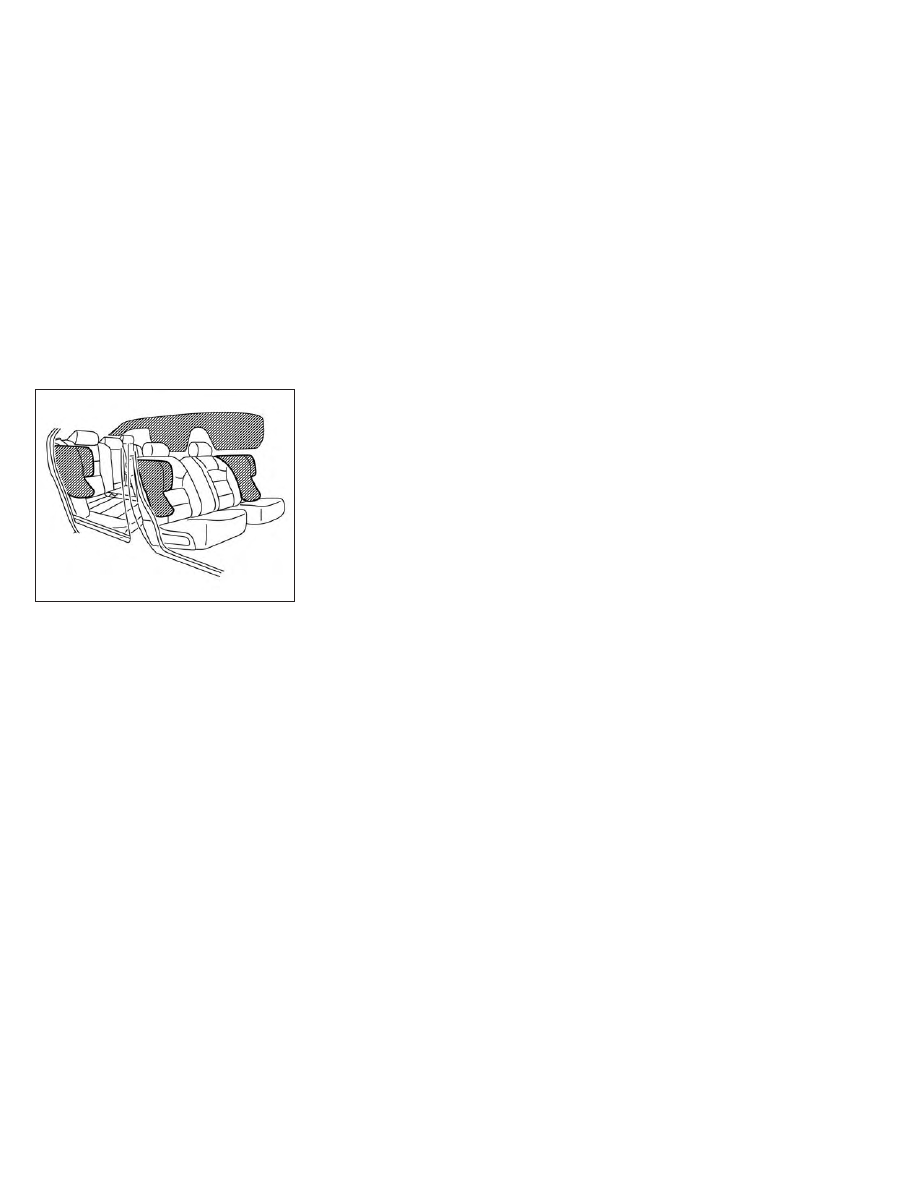
Front and rear outboard
seat-mounted side-impact
supplemental air bag and
roof-mounted curtain
side-impact and rollover
supplemental air bag systems

The side air bags are located in the outside
of the seatback of the front seats and rear
outboard seats. The curtain air bags are
located in the side roof rails.

All of the in-

formation, cautions, and warnings in this
manual apply and must be followed.

The

side air bags and curtain air bags are de-
signed to inflate in higher severity side col-

lisions, although they may inflate if the
forces in another type of collision are simi-
lar to those of a higher severity side impact.
They are designed to inflate on the side
where the vehicle is impacted. They may
not inflate in certain side collisions on the
side where the vehicle is impacted.

The curtain air bags are also designed to
inflate in certain types of rollover collisions
or near rollovers. As a result, certain vehicle
movements (for example, during severe
off-roading) may cause the curtain air
bags to inflate.

Vehicle damage (or lack of it) is not always
an indication of proper side air bag and
curtain air bag operation.

When the side air bags and curtain air bags
inflate, a fairly loud noise may be heard,
followed by release of smoke. This smoke is
not harmful and does not indicate a fire.
Care should be taken not to inhale it, as it
may cause irritation and choking. Those
with a history of a breathing condition
should get fresh air promptly.

Side air bags, along with the use of seat
belts, help to cushion the impact force on
the chest and pelvic area of the front and
rear outboard occupants. Curtain air bags
help to cushion the impact force to the

head of occupants in the front and rear
outboard seating positions. They can help
save lives and reduce serious injuries. How-
ever, side air bags and curtain air bags may
cause abrasions or other injuries. Side air
bags and curtain air bags do not provide
restraint to the lower body.

The seat belts should be correctly worn
and the driver, front passenger and rear
outboard occupants seated upright as far
as practical away from the side air bags.
Rear seat passengers should be seated as
far away as practical from the door finish-
ers and side roof rails. The side air bags and
curtain air bags inflate quickly in order to
help protect the occupants in the outboard
seating positions. Because of this, the force
of the side air bags and curtain air bags
inflating can increase the risk of injury if the
occupant is too close to, or is against, these
air bag modules during inflation. The side
air bags and curtain air bags will deflate
quickly after the collision is over.

The side air bags and curtain air bags
operate only when the power switch is in
the ON position.

LRS3142

Safety–Seats, seat belts and supplemental restraint system

1-61

-------------------------------------------------------------------------------------------------------------------------------------------------------------

After turning the power switch to the ON
position,

the

supplemental

air

bag

warning light illuminates. The supple-
mental air bag warning light will turn off
after about 7 seconds if the systems are
operational.

WARNING

Do not place any objects near the
seatback of the front and rear seats.
Also, do not place any objects (an
umbrella, bag, etc.) between the front
and rear door finishers and the front
and rear seats. Such objects may be-
come

dangerous

projectiles

and

cause injury if a side air bag inflates.

Right after inflation, several side air
bag and curtain air bag system com-
ponents will be hot. Do not touch
them;

you

may

severely

burn

yourself.

No unauthorized changes should be
made to any components or wiring
of the side air bag and curtain air bag
systems. This is to prevent damage
to or accidental inflation of the side
air bag and curtain air bag systems.

Do not make unauthorized changes
to your vehicle’s electrical system,
suspension system or side panel.
This could affect proper operation of
the side air bag and curtain air bag
systems.

Tampering with the side air bag sys-
tem may result in serious personal
injury. For example, do not change
the front and rear seats by placing
material near the seatbacks or by in-
stalling

additional

trim

material,

such as seat covers, around the side
air bag.

It is recommended that you visit a
NISSAN certified LEAF dealer for work
around and on the side air bag and
curtain air bag systems. It is also rec-
ommended that you visit a NISSAN
certified LEAF dealer for installation
of electrical equipment. The Supple-
mental Restraint System (SRS) wiring
harnesses* should not be modified or
disconnected. Unauthorized electri-
cal test equipment and probing de-
vices should not be used on the side
air bag and curtain supplemental air
bag systems.

*The SRS wiring harness connectors are
yellow

and

orange

for

easy

identification.

When selling your vehicle, we request that
you inform the buyer about the side air bag
and curtain air bag systems and guide the
buyer to the appropriate sections in this
Owner’s Manual.

1-62

Safety–Seats, seat belts and supplemental restraint system

-------------------------------------------------------------------------------------------------------------------------------------------------------------

Driver and front passenger
supplemental knee air bag

The knee air bag is located in the knee
bolster, on the driver’s and passenger’s
side.

All of the information, cautions and

warnings in this manual apply and must
be followed.

The knee air bag is designed

to inflate in higher severity frontal collisions,
although it may inflate if the forces in an-
other type of collision are similar to those of
a higher severity frontal impact. It may not
inflate in certain collisions.

Vehicle damage (or lack of it) is not always
an indication of proper knee air bag
operation.

When the knee air bag inflates, a fairly loud
noise may be heard, followed by release of
smoke. This smoke is not harmful and
does not indicate a fire. Care should be
taken not to inhale it, as it may cause irrita-
tion and choking. Those with a history of a
breathing condition should get fresh air
promptly.

The knee air bag helps to cushion the im-
pact force on the knees of the driver and
passenger. It can help reduce serious inju-
ries. However, an inflating knee air bag may
cause abrasions or other injuries. The knee
air bag provides restraint to the lower body.

The knee air bag inflates quickly in order to
help protect the occupants. Because of
this, the force of the knee air bag inflating
can increase the risk of injury if the occu-
pant is too close to, or is against, this air bag
module during inflation. The knee air bag
will deflate quickly after the collision is over
OR the knee air bag will remain inflated for
a short time.

The knee air bag operates only when the
power switch is placed in the ON
position.

After placing the power switch in the ON
position,

the

supplemental

air

bag

warning light illuminates. The supple-
mental air bag warning light will turn off
after about 7 seconds if the system is
operational.

LRS3347

Driver’s side

LRS3250

Passenger’s side

Safety–Seats, seat belts and supplemental restraint system

1-63

-------------------------------------------------------------------------------------------------------------------------------------------------------------

WARNING

Do not place any objects between the
knee bolster and the driver’s or pas-
senger’s seat. Such objects may be-
come

dangerous

projectiles

and

cause injury if a knee air bag inflates.

Right after inflation, the knee air bag
system components will be hot. Do
not touch them; you may severely
burn yourself.

No unauthorized changes should be
made to any components or wiring
of the knee air bag system. This is to
prevent damage to or accidental in-
flation of the knee air bag system.

Do not make unauthorized changes
to your vehicle's electrical system or
suspension system. This could affect
proper operation of the knee air bag
system.

Tampering with the knee air bag sys-
tem may result in serious personal
injury. For example, do not change
the driver or passenger knee bolster
or install additional trim material
around the knee air bag.

It is recommended that you visit a
NISSAN certified LEAF dealer for work
on and around the knee air bag. It is
also recommended that you visit a
NISSAN certified LEAF dealer for in-
stallation of electrical equipment.
The SRS wiring harnesses* should
not be modified or disconnected. Un-
authorized electrical test equipment
and probing devices should not be
used on the knee air bag system.

*The SRS wiring harness or connectors
are

yellow

or

orange

for

easy

identification.

When selling your vehicle, we request that
you inform the buyer about the knee air
bag system and guide the buyer to the
appropriate sections in this manual.

Seat belt with pretensioner(s)
(front and rear outboard seats)

WARNING

The pretensioner(s) cannot be re-
used after activation. They must be
replaced together with the retractor
and buckle as a unit.

If the vehicle becomes involved in a
collision but pretensioner(s) are not
activated, be sure to have the preten-
sioner system checked and, if neces-
sary, replaced. It is recommended
that you visit a NISSAN certified LEAF
dealer for this service.

No unauthorized changes should be
made to any components or wiring
of the pretensioner system. This is to
prevent damage to or accidental ac-
tivation of the pretensioner(s). Tam-
pering with the pretensioner system
may result in serious personal injury.

It is recommended that you visit a
NISSAN certified LEAF dealer for work
around and on the pretensioner sys-
tem. It is also recommended that you
visit a NISSAN certified LEAF dealer
for installation of electrical equip-
ment. Unauthorized electrical test
equipment

and

probing

devices

should not be used on the preten-
sioner system.

If you need to dispose of the preten-
sioner(s) or scrap the vehicle, it is rec-
ommended that you visit a NISSAN
certified LEAF dealer for this service.
Incorrect disposal procedures could
cause personal injury.

1-64

Safety–Seats, seat belts and supplemental restraint system

-------------------------------------------------------------------------------------------------------------------------------------------------------------

The pretensioner system may activate
with the supplemental air bag system in
certain types of collisions. Working with the
seat belt retractor, the pretensioner(s) help
tighten the seat belt when the vehicle be-
comes involved in certain types of colli-
sions, helping to restrain front and rear out-
board seat occupants.

The pretensioner(s) are encased with the
seat belt retractor and to the seat belt an-
chor affixed to the floor of the vehicle.
These seat belts are used the same way as
conventional seat belts.

When pretensioner(s) activate, smoke is re-
leased and a loud noise may be heard. This
smoke is not harmful and does not indi-
cate a fire. Care should be taken not to
inhale it, as it may cause irritation and
choking. Those with a history of a breath-
ing condition should get fresh air promptly.

After the pretensioner(s’) activation, load
limiters allow the seat belt to release web-
bing (if necessary) to reduce forces against
the chest.

The supplemental air bag warning light

is used to indicate malfunctions in the

pretensioner system. For additional infor-
mation, see “Supplemental air bag warning
light” (P. 1-66). If the operation of the supple-
mental air bag warning light indicates
there is a malfunction, have the system
checked. It is recommended that you visit a
NISSAN certified LEAF dealer for this
service.

When selling your vehicle, we request that
you inform the buyer about the preten-
sioner system and guide the buyer to the
appropriate

sections

in

this

Owner’s

Manual.

SUPPLEMENTAL AIR BAG WARNING
LABELS

LRS2620

A. Supplemental front-impact air bag sys-

tem warning labels

Safety–Seats, seat belts and supplemental restraint system

1-65

-------------------------------------------------------------------------------------------------------------------------------------------------------------

SUPPLEMENTAL AIR BAG WARNING
LIGHT

The supplemental air bag warning light,
displaying

in the instrument panel,

monitors the circuits of the Air bag Control
Unit (ACU), satellite sensors, crash zone
sensor, occupant classification sensor, the
supplemental front-impact air bag, front
and rear outboard seat-mounted side-
impact

supplemental

air

bag,

roof-

mounted curtain side-impact supplemen-
tal air bag, knee air bag and seat belt
pretensioner systems. The monitored cir-

cuits include air bag systems, pretension-
er(s) and all related wiring.

When the power switch is in the ON posi-
tion, the supplemental air bag warning
light illuminates for about 7 seconds and
then turns off. This means the system is
operational.

If any of the following conditions occur, the
front air bag, side air bag, curtain air bag,
knee air bag and pretensioner systems
need servicing:
• The supplemental air bag warning light

remains

on

after

approximately

7

seconds.

• The supplemental air bag warning light

flashes intermittently.

• The supplemental air bag warning light

does not come on at all.

Under these conditions, the front air bag,
side air bag, curtain air bag, knee air bag
and pretensioner systems may not oper-
ate properly. They must be checked and
repaired. It is recommended that you visit
the nearest NISSAN certified LEAF dealer
for this service.

WARNING

If the supplemental air bag warning
light is on, it could mean that the front
air bag, side air bag, curtain air bag,
knee air bag and/or pretensioner sys-
tems will not operate in an accident. To
help avoid injury to yourself or others,
have your vehicle checked as soon as
possible. It is recommended that you
visit a NISSAN certified LEAF dealer for
this service.

Repair and replacement
procedure

The front air bags, side air bags, curtain air
bags, knee air bags and pretensioner(s) are
designed to activate on a one-time-only
basis. As a reminder, unless it is damaged,
the supplemental air bag warning light will
remain illuminated after inflation has oc-
curred. These systems should be repaired
and/or replaced as soon as possible. It is
recommended that you visit a NISSAN cer-
tified LEAF dealer for this service.

SPA1097

1-66

Safety–Seats, seat belts and supplemental restraint system

-------------------------------------------------------------------------------------------------------------------------------------------------------------

When maintenance work is required on the
vehicle, the front air bags, side air bags,
curtain air bags, knee air bags and preten-
sioner(s) and related parts should be
pointed out to the person performing the
maintenance. The power switch should al-
ways be in the LOCK position when work-
ing under the hood or inside the vehicle.

WARNING

Once a front air bag, side air bag, cur-
tain air bag or knee air bag has in-
flated, the air bag module will not
function again and must be replaced.
Additionally, the activated preten-
sioner(s) must also be replaced. The
air bag module and pretensioner(s)
should be replaced. It is recom-
mended that you visit a NISSAN cer-
tified LEAF dealer for this service. The
air bag modules and pretensioner
system cannot be repaired.

The front air bag, side air bag, curtain
air bag and knee air bag systems,
and pretensioner system should be
inspected if there is any damage to
the front end or side portion of the
vehicle. It is recommended that you
visit a NISSAN certified LEAF dealer
for this service.

If you need to dispose of a supple-
mental air bag or pretensioner sys-
tem or scrap the vehicle, it is recom-
mended that you visit a NISSAN
certified LEAF dealer for this service.
Correct supplemental air bag and
pretensioner system disposal proce-
dures are set forth in the appropriate
NISSAN Service Manual. Incorrect
disposal

procedures

could

cause

personal injury.

If there is an impact to your vehicle
from any direction, your Occupant
Classification Sensor (OCS) should be
checked. It is recommended that you
visit a NISSAN certified LEAF dealer to
verify it is still functioning correctly.
The OCS should be checked even if no
air bags deploy as a result of the im-
pact. Failure to verify proper OCS
function may result in an improper
air bag deployment resulting in in-
jury or death.

Safety–Seats, seat belts and supplemental restraint system

1-67

-------------------------------------------------------------------------------------------------------------------------------------------------------------

2 Instruments and controls

Cockpit . . . . . . . . . . . . . . . . . . . . . . . . . . . . . . . . . . . . . . . . . 2-2
Instrument Panel . . . . . . . . . . . . . . . . . . . . . . . . . . . . . . . . 2-4
Meters and Gauges . . . . . . . . . . . . . . . . . . . . . . . . . . . . . 2-5

Speedometer and odometer . . . . . . . . . . . . . . . . . 2-5
Li-ion battery temperature gauge . . . . . . . . . . . . 2-7
Power meter . . . . . . . . . . . . . . . . . . . . . . . . . . . . . . . . . 2-7
Driving range . . . . . . . . . . . . . . . . . . . . . . . . . . . . . . . . . 2-8
Li-ion battery available charge gauge . . . . . . . . 2-9
Li-ion battery capacity level gauge . . . . . . . . . . 2-12
Outside air temperature . . . . . . . . . . . . . . . . . . . . . 2-12
Clock . . . . . . . . . . . . . . . . . . . . . . . . . . . . . . . . . . . . . . . . 2-12
ECO mode indicator . . . . . . . . . . . . . . . . . . . . . . . . . 2-13
e-Pedal system indicator . . . . . . . . . . . . . . . . . . . . 2-13

Warning lights, indicator lights and audible
reminders . . . . . . . . . . . . . . . . . . . . . . . . . . . . . . . . . . . . . . 2-14

Checking lights . . . . . . . . . . . . . . . . . . . . . . . . . . . . . . 2-16
Warning/Indicator lights (red) . . . . . . . . . . . . . . . 2-16
Warning/Indicator lights (yellow) . . . . . . . . . . . . 2-19
Warning/Indicator lights (other) . . . . . . . . . . . . . 2-24
Audible reminders . . . . . . . . . . . . . . . . . . . . . . . . . . . 2-25

Vehicle information display . . . . . . . . . . . . . . . . . . . . . 2-26

How to use the vehicle information
display . . . . . . . . . . . . . . . . . . . . . . . . . . . . . . . . . . . . . . 2-27
Startup display . . . . . . . . . . . . . . . . . . . . . . . . . . . . . . 2-27
Settings . . . . . . . . . . . . . . . . . . . . . . . . . . . . . . . . . . . . . 2-28
Vehicle information display warnings
and indicators . . . . . . . . . . . . . . . . . . . . . . . . . . . . . . . 2-36

Warning information displays
(models with a navigation system) . . . . . . . . . . 2-44

Security systems . . . . . . . . . . . . . . . . . . . . . . . . . . . . . . . 2-44

Vehicle security system . . . . . . . . . . . . . . . . . . . . . 2-44
NISSAN Vehicle Immobilizer System . . . . . . . . . 2-46

Wiper and washer switch . . . . . . . . . . . . . . . . . . . . . . . 2-47

Washer operation . . . . . . . . . . . . . . . . . . . . . . . . . . . 2-48
Rear wiper operation . . . . . . . . . . . . . . . . . . . . . . . . 2-48

Rear window and outside mirror
(if so equipped) defroster switch . . . . . . . . . . . . . . . 2-49
Headlight and turn signal switch . . . . . . . . . . . . . . . 2-50

Headlight switch . . . . . . . . . . . . . . . . . . . . . . . . . . . . 2-50
LED Daytime Running Lights (DRL)
system (Type A) (if so equipped) . . . . . . . . . . . . . 2-55
LED Daytime Running Lights (DRL)
system (Type B) (if so equipped) . . . . . . . . . . . . . 2-55
Instrument brightness control . . . . . . . . . . . . . . 2-56
Turn signal switch . . . . . . . . . . . . . . . . . . . . . . . . . . . 2-56
Fog light switch (if so equipped) . . . . . . . . . . . . . 2-57
Emblem Light . . . . . . . . . . . . . . . . . . . . . . . . . . . . . . . 2-57

Horn . . . . . . . . . . . . . . . . . . . . . . . . . . . . . . . . . . . . . . . . . . . 2-58
ECO switch . . . . . . . . . . . . . . . . . . . . . . . . . . . . . . . . . . . . . 2-58
Heated seat switches (if so equipped) . . . . . . . . . . 2-58
Heated steering wheel switch (if so equipped) . . 2-60
Emergency call (SOS) button (if so equipped) . . . 2-60
Charge port lid switch . . . . . . . . . . . . . . . . . . . . . . . . . . 2-61

-------------------------------------------------------------------------------------------------------------------------------------------------------------

Immediate Charge switch . . . . . . . . . . . . . . . . . . . . . . 2-61
Dynamic driver assistance switch
(for vehicles without ProPILOT Assist)
(if so equipped) . . . . . . . . . . . . . . . . . . . . . . . . . . . . . . . . . 2-61
Steering Assist switch (for models with
ProPILOT Assist) (if so equipped) . . . . . . . . . . . . . . . . 2-62
Rear Door Alert . . . . . . . . . . . . . . . . . . . . . . . . . . . . . . . . . 2-62
Power outlet . . . . . . . . . . . . . . . . . . . . . . . . . . . . . . . . . . . 2-64
USB/iPod® charging ports . . . . . . . . . . . . . . . . . . . . . . 2-64
Storage . . . . . . . . . . . . . . . . . . . . . . . . . . . . . . . . . . . . . . . . 2-65

Seatback Pocket (if so equipped) . . . . . . . . . . . . 2-65
Storage tray . . . . . . . . . . . . . . . . . . . . . . . . . . . . . . . . . 2-65
Glove box . . . . . . . . . . . . . . . . . . . . . . . . . . . . . . . . . . . 2-66

Console box . . . . . . . . . . . . . . . . . . . . . . . . . . . . . . . . . 2-66
Overhead sunglasses storage . . . . . . . . . . . . . . . 2-66
Cup holders . . . . . . . . . . . . . . . . . . . . . . . . . . . . . . . . . 2-67
Tonneau cover (if so equipped) . . . . . . . . . . . . . . 2-68
Stowing golf bags . . . . . . . . . . . . . . . . . . . . . . . . . . . 2-69

Windows . . . . . . . . . . . . . . . . . . . . . . . . . . . . . . . . . . . . . . . 2-69

Power windows . . . . . . . . . . . . . . . . . . . . . . . . . . . . . 2-69

Interior lights . . . . . . . . . . . . . . . . . . . . . . . . . . . . . . . . . . . 2-72

Console light (if so equipped) . . . . . . . . . . . . . . . . 2-72
Map lights . . . . . . . . . . . . . . . . . . . . . . . . . . . . . . . . . . . 2-73
Room light . . . . . . . . . . . . . . . . . . . . . . . . . . . . . . . . . . 2-73
Cargo light . . . . . . . . . . . . . . . . . . . . . . . . . . . . . . . . . . 2-73

-------------------------------------------------------------------------------------------------------------------------------------------------------------

1.

TRIP RESET switch for twin trip
odometer (P. 2-5)
Instrument brightness control switch
(P. 2-56)

2.

Headlight, fog light (if so equipped) and
turn signal switch (P. 2-50, 2-57, 2-56)

3.

Steering-wheel-mounted controls (left
side)
Audio control*
Vehicle information display controls
(P. 2-26)

4.

Steering wheel (P. 3-22)
Power steering system (P. 5-161)
Horn (P. 2-58)
Driver's supplemental air bag (P. 1-44)

5.

Wiper and washer switch (P. 2-47)

6.

Steering-wheel-mounted controls
(right side)
Cruise control switches (if so equipped)
(P. 5-65)
Intelligent Cruise Control (ICC) switches
(if so equipped) (P. 5-67)
ProPILOT Assist switch (if so equipped)
(P. 5-92)
Bluetooth® Hands-Free Phone System
control*

7.

Shift lever (P. 5-14)
ECO switch (P. 2-58)
e-Pedal switch (P. 5-21)

8.

Console box (P. 2-66)

9.

Parking brake (switch type)
(if so equipped) (P. 5-19)

10.

Tilt and telescopic steering wheel lever
(P. 3-23)

LII2624

COCKPIT

2-2

Instruments and controls

-------------------------------------------------------------------------------------------------------------------------------------------------------------

11.

Lower instrument panel switches
Charge port lid switch (P. 2-61)
Immediate charge switch (P. 2-61)
Heated steering wheel switch
(if so equipped) (P. 2-60)
Steering Assist switch (if so equipped)
(P. 2-62)
Dynamic driver assistance switch
(if so equipped) (P. 5-25, 5-30, 5-45, 2-61)

12.

Fuse box cover (P. 8-15)

*For additional information, refer to the
NissanConnect® Manual

Instruments and controls

2-3

-------------------------------------------------------------------------------------------------------------------------------------------------------------

1.

Vents (P. 4-28)

2.

Meters and gauges (P. 2-5)
Vehicle information display (P. 2-26)

3.

Center multi-function control panel*

4.

Hazard warning flasher switch (P. 6-2)

5.

Rear window and outside mirror
(if so equipped) defroster switch (P. 2-49)

6.

Front passenger supplemental air bag
(P. 1-44)

7.

Glove box (P. 2-66)

8.

Front passenger supplemental knee
airbag (P. 1-63)

9.

Heater and air conditioner control
(P. 4-29)

10.

Power outlet (P. 2-64)

11.

Front heated seat switches
(if so equipped) (P. 2-58)

12.

USB connection port*

13.

Push-button power switch (P. 5-9)

14.

Front passenger air bag status light
(P. 1-55)

15.

Driver supplemental knee air bag
(P. 1-63)

16.

Hood release handle (P. 3-18)

LII2625

INSTRUMENT PANEL

2-4

Instruments and controls

-------------------------------------------------------------------------------------------------------------------------------------------------------------

1.

Vehicle information display (P. 2-26)
Clock (P. 2-34)
Outside air temperature (P. 2-12)

Li-ion battery available charge gauge
(P. 2-9)
Driving range (P. 2-8)
Odometer/twin trip odometer (P. 2-5)

Indicator for timer (P. CH-46)
Power meter (P. 2-7)
ECO mode indicator (P. 2-13)

2.

Warning and indicator lights (P. 2-14)
Turn signal/Hazard indicator light
(P. 2-25)
READY to drive indicator light (P. 2-25)

3.

Speedometer (P. 2-5)

SPEEDOMETER AND ODOMETER

The vehicle is equipped with a speedom-
eter and odometer. The speedometer is
located on the right side of the vehicle in-
formation display. The odometer is located
within the vehicle information display.

LIC3861

METERS AND GAUGES

Instruments and controls

2-5

-------------------------------------------------------------------------------------------------------------------------------------------------------------

Speedometer

The speedometer indicates the vehicle
speed.

Odometer/twin trip odometer

The odometer and twin trip odometer

O

2

are displayed on the vehicle information
display when the power switch is in the ON
or READY to drive position.

The odometer records the total distance
the vehicle has been driven.

The twin trip odometer records the dis-
tance of individual trips.

Changing the display:

Pushing the TRIP RESET switch

O

1

located

on the left side of the instrument panel
changes the display as follows:

Odometer

TRIP A

TRIP B

Odometer

For additional information about the ve-
hicle information display, see “Vehicle infor-
mation display” (P. 2-26).

Resetting the trip odometer:

Pushing the TRIP RESET switch

O

1

for ap-

proximately 1 second resets the currently
displayed trip odometer to zero.

LIC3862

LIC3863

2-6

Instruments and controls

-------------------------------------------------------------------------------------------------------------------------------------------------------------

LI-ION BATTERY TEMPERATURE
GAUGE

The gauge indicates the temperature of
the Li-ion battery.

The temperature of the Li-ion battery is
within the normal range when the display
is within the zone

O

1

shown in the

illustration.

The temperature of the Li-ion battery var-
ies according to the outside air tempera-
ture and driving conditions.

NOTE:
• If the display indicates that the tem-

perature of the Li-ion battery is near
the red zone end of the normal range,
reduce vehicle speed to decrease the
temperature. If the indicator is over the
normal range, the power provided to
the traction motor is reduced when the
power limitation indicator light is illu-
minated. Therefore, the vehicle is not
as responsive when the accelerator is
depressed while the power limitation
light is illuminated. For additional in-
formation, see “Power limitation indi-
cator light” (P. 2-23).

• If the outside temperature is extremely

low, the Li-ion temperature gauge may
not display a temperature reading. The
vehicle may not be able to be put in the
READY to drive mode. Have the system
checked. It is recommended that you
visit a NISSAN certified LEAF dealer for
this service.

POWER METER

This meter displays the actual traction mo-
tor power consumption

O

A

and the regen-

erative brake power provided to the Li-ion
battery

O

B

.

The power meter is in a neutral state

O

3

.

The white illuminated portion

O

1

in the dis-

play moves right or left depending on
demand.

The white illuminated portion

O

1

moves to

the right when power is provided to the
traction motor (Li-ion battery discharges).

LIC3875

LIC3864

Instruments and controls

2-7

-------------------------------------------------------------------------------------------------------------------------------------------------------------

The white illuminated portion

O

1

moves to

the left when power is generated and pro-
vided to the Li-ion battery by the regenera-
tive brake system (Li-ion battery charging).

The power meter also indicates if the
power provided to the motor is limited or if
regenerative

braking

is

limited. When

power or regenerative braking is limited,
the illuminated segments on the display
are narrowed

O

2

.

Regenerative braking is automatically re-
duced when the Li-ion battery is fully
charged to prevent the Li-ion battery from
becoming

overcharged.

Regenerative

braking is also automatically reduced

when the Li-ion battery temperature is
high/low (indicated by the red/blue zones
on the Li-ion battery temperature gauge)
to prevent Li-ion battery damage.

The more regenerative braking is reduced,
the more illuminated segments on the dis-
play are narrowed

O

2

.

If the Li-ion battery charge is low, power
provided to the traction motor is reduced.
Motor output is also limited if the Li-ion
battery temperature is high/low (indicated
by the red/blue zones on the Li-ion battery
temperature gauge) or the Li-ion battery
charge level is low.

The more power provided to the traction
motor is reduced, the more illuminated
segments on the display are narrowed

O

2

.

NOTE:

If the power meter is selected on the trip
computer, the meter is not displayed.

DRIVING RANGE

The driving range

O

1

provides an esti-

mated distance that the vehicle can be
driven before recharging is necessary. The
driving range is constantly being calcu-
lated, based on the amount of available
Li-ion battery charge and the actual power
consumption average.

When the power switch is placed in the OFF
position, it remains for approximately 30
seconds.

LIC3865

LIC5001

2-8

Instruments and controls

-------------------------------------------------------------------------------------------------------------------------------------------------------------


Content      ..     9      10      11      12     ..