Nissan Titan (2023 year). Manual in english - page 37
Symbol Name
Reference
Graphic
Caution
ISO 7000 0434
Air Conditioning System
(MAC)
ISO 2575 D01
MAC System Lubricant Type
(PAG–POE)
Requires Registered Technician to
Service MAC System
Flammable Refrigerant
Air Conditioner Specification Label Symbols
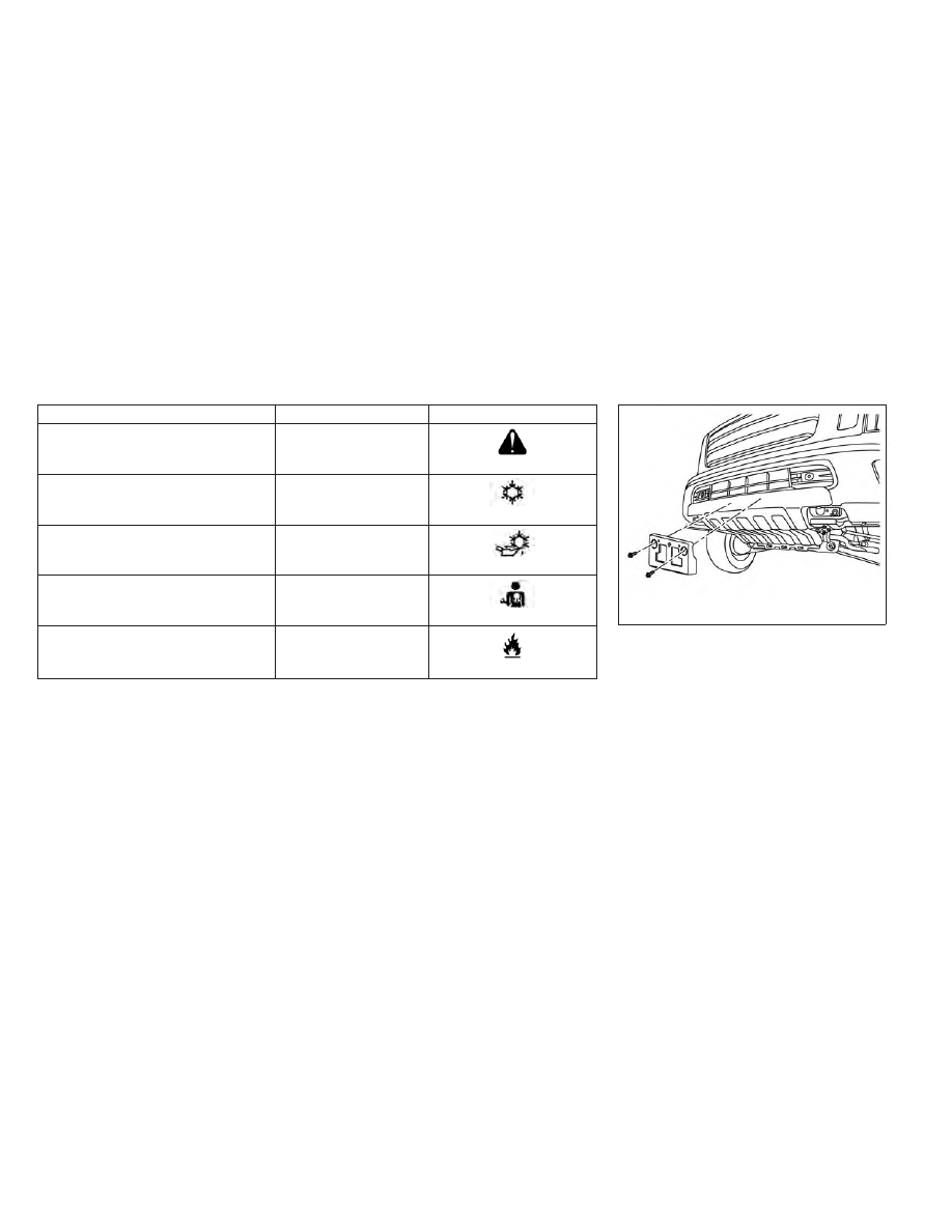
Use the following steps to mount the front
license plate:
1. Attach the license plate bracket on the
skid plate at the location marked (small
dimple) using self-tapping screws.
LTI2685
Pro-4X
INSTALLING FRONT LICENSE PLATE
Technical and consumer information
10-19