Nissan Qashqai (2022 year). Manual in english - page 24
other maneuvers. Always look
around and check that it is safe
to do so before parking.
.
Read and understand the limita-
tions of the RSS as contained in
this section. The colors of the
sonar indicator and the distance
guide lines in the rear view in-
dicate different distances to the
object.
.
Inclement weather or ultrasonic
sources such as an automatic car
wash, a truck’s compressed-air
brakes or a pneumatic drill may
affect the function of the system;
this may include reduced perfor-
mance or a false activation.
.
The RSS is designed as an aid to
the driver in detecting large sta-
tionary objects to help avoid da-
maging the vehicle.
.
The RSS is not designed to pre-
vent contact with small or mov-
ing objects. Always move slowly.
The system will not detect small
objects below the bumper, and
may not detect objects close to
the bumper or on the ground.
.
The RSS may not detect the
following objects: fluffy objects
such as snow, cloth, cotton, glass,
wool, etc.; thin objects such as
rope, wire and chain, etc.; or
wedge-shaped objects.
.
The RSS detects the distance
between the vehicle and the ob-
stacle by detecting the sound
wave reflected from the surface
of an obstacle. When there is a
sound such as horn, or an ultra-
sonic source (such as sonar of
other vehicles) around the vehi-
cle, the sonar may not detect
objects properly.
If your vehicle sustains damage to the
bumper fascia, leaving it misaligned or
bent, the sensing zone may be altered
causing inaccurate measurement of ob-
stacles or false alarms.
CAUTION
.
Excessive noise (such as audio
system volume or an open vehi-
cle window) will interfere with the
tone and it may not be heard.
.
Keep the sonar sensors (located
on the rear bumper fascia) free
from snow, ice and large accu-
mulations of dirt. Do not clean the
sensors with sharp objects. If the
sensors are covered, the accuracy
of the sonar function will be
diminished.
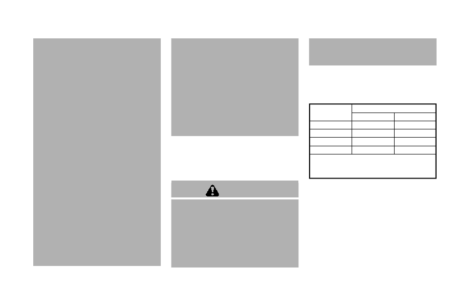
SYSTEM OPERATION
The system informs with a visual and
audible alert of rear obstacles when the
shift lever is in the R (Reverse) position.
Range
Rear sonar
Sound
Display
P (Park)
B
C
R (Reverse)
O
O
N (Neutral)
B
C
D (Drive)
B
C
O = Display / Beep when detect
C = Display on camera view
B = No display and beep
The system is deactivated at speeds
above 6 MPH (10 km/h). It is reactivated
at lower speeds.
The intermittent tone will stop after 3
seconds when an obstacle is detected by
only the corner sensor and the distance
does not change. The tone will stop when
the obstacle gets away from the vehicle.
When the object is detected, the indicator
(green) appears and blinks and the tone
sounds intermittently. When the vehicle
moves closer to the object, the color of
Starting and driving
5-137