Nissan Versa (2022 year). Manual in english - page 21
CAUTION
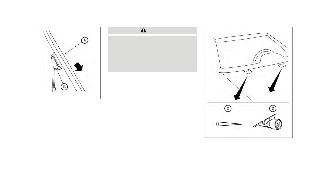
• After wiper blade replacement, re-
turn the wiper arm to its original po-
sition; otherwise it may be damaged
when the hood is opened.
• Make sure the wiper blades contact
the glass; otherwise the arms may be
damaged from wind pressure.
LDI2757
REPLACING
Replace the wiper blades if they are worn.
To replace the windshield wiper blades, fol-
low the procedure below:
1. Lift the wiper arm away from the
windshield.
LDI2731
B .
If you wax the surface of the hood, be care-
ful not to let wax get into the washer nozzle
A down and
D . This may cause clogging or improper
remove.
windshield-washer operation. If wax gets
4. Insert the new wiper blade onto the
into the nozzle, remove it with a needle or
wiper arm until it clicks into place.
C .
5. Push wiper on to windshield.
Do-it-yourself
8-17

BRAKES
FUSES
If the brakes do not operate properly, have
Under some driving or climate conditions,
the brakes checked. It is recommended
occasional brake squeak, squeal or other
that you visit a NISSAN dealer for this
noise may be heard. Occasional brake
service.
noise during light to moderate stops is nor-
mal and does not affect the function or
Self-adjusting brakes
performance of the brake system.
Your vehicle is equipped with self-adjusting
Proper brake inspection intervals should
brakes.
be followed. For additional information re-
garding brake inspections, refer to the ap-
The front disc-type brakes self-adjust ev-
propriate maintenance schedule informa-
ery time the brake pedal is applied. The rear
tion in the "Maintenance and schedules"
drum-type brakes self-adjust every time
section of this manual.
the parking brake is applied.
WARNING
LDI2997
Have your brake system checked if the
If any electrical equipment does not oper-
brakes pedal height does not return to
ate, check for an open fuse.
normal. It is recommended that you
Fuses are used in the passenger compart-
visit a NISSAN dealer for this service.
ment. Spare fuses are provided and can be
found in the passenger compartment fuse
Brake pad wear indicators
box.
The disc brake pads on your vehicle have
When installing a fuse make sure the fuse is
audible wear indicators. When a brake pad
installed in the fuse box securely.
requires replacement, a high pitched
scraping or screeching sound will be heard
when the vehicle is in motion. The noise will
be heard whether or not the brake pedal is
depressed. Have the brakes checked as
soon as possible if the wear indicator
sound is heard.
8-18
Do-it-yourself
3. Remove the fuse box cover by pushing
the tab and lifting the cover up.
4. Remove the fuse with the fuse puller.
The fuse puller is located in the center of
the fuse block in the passenger
compartment.
LDI3527
LDI3232
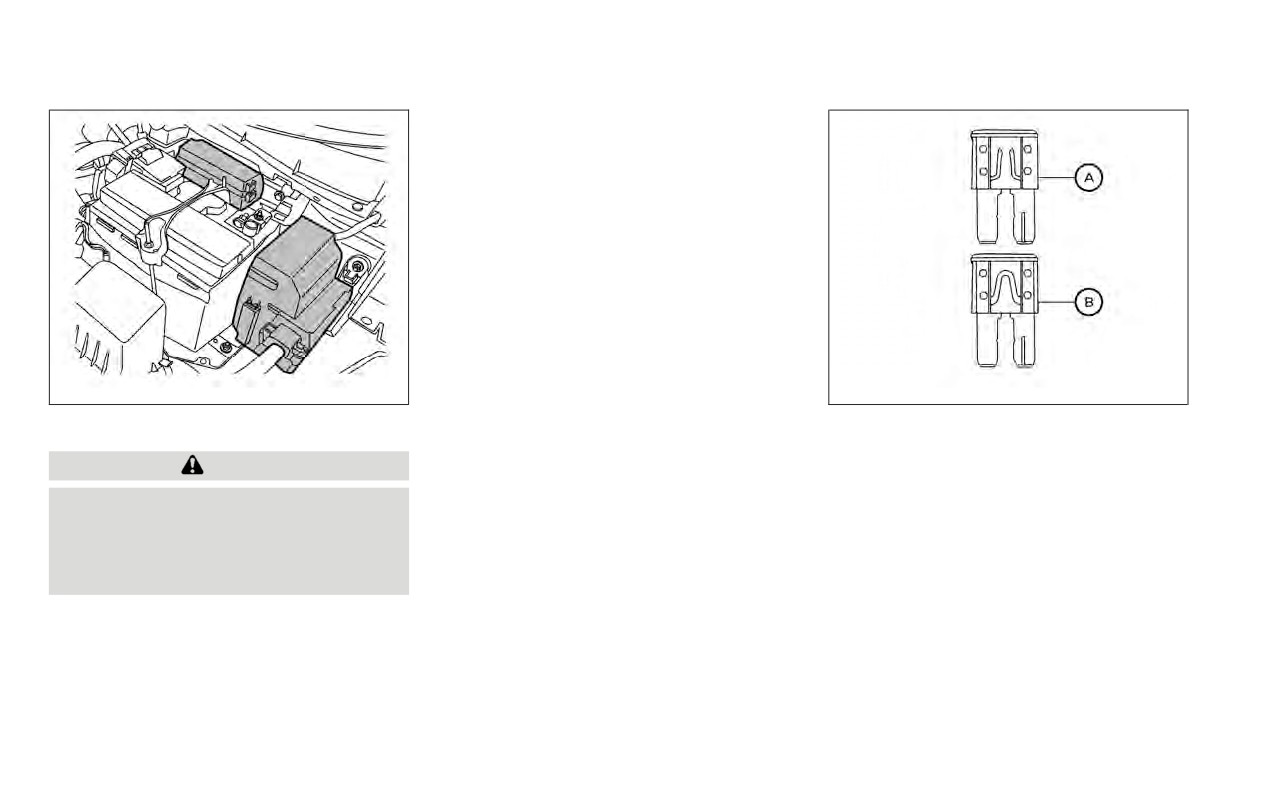
ENGINE COMPARTMENT
A , replace it with a
B .
CAUTION
6. If a new fuse also opens, have the elec-
trical system checked and repaired. It is
Never use a fuse of higher or lower am-
recommended that you visit a NISSAN
perage rating than that specified on
dealer for this service.
the fuse box cover. This could damage
the electrical system or electronic con-
Fusible links
trol units or cause a fire.
If any electrical equipment does not oper-
ate and the fuses are in good condition,
If any electrical equipment does not come
check the fusible links in the holder. If any of
on, check for an open fuse.
the fusible links are melted, replace only
1. Be sure the ignition switch and the head-
with Genuine NISSAN parts.
light switch are OFF.
For checking and replacing the fusible links,
it is recommended that you visit a NISSAN
2. Open the engine hood.
dealer for this service.
Do-it-yourself
8-19

LDI3087
LDI2998
PASSENGER COMPARTMENT
1.
Be sure the ignition switch and the head-
C , replace it with an
light switch are OFF.
D .
CAUTION
2.
A with a
6. Push the fuse box cover to install.
suitable tool. Use a cloth to avoid dam-
Never use a fuse of a higher or lower
If a new fuse also opens, have the electrical
aging the trim.
amperage rating than that specified on
system checked and repaired. It is recom-
the fuse box cover. This could damage
3.
Locate the fuse that needs to be
mended that you visit a NISSAN dealer for
the electrical system or electronic con-
replaced.
this service.
trol units or cause a fire.
4.
B .
NOTE:
If any electrical equipment does not oper-
Your vehicle may not be equipped with
ate, check for an open fuse.
all fuses listed on the fuse label.
NOTE:
The fuse box is located on the driver's
side of the instrument panel.
8-20
Do-it-yourself
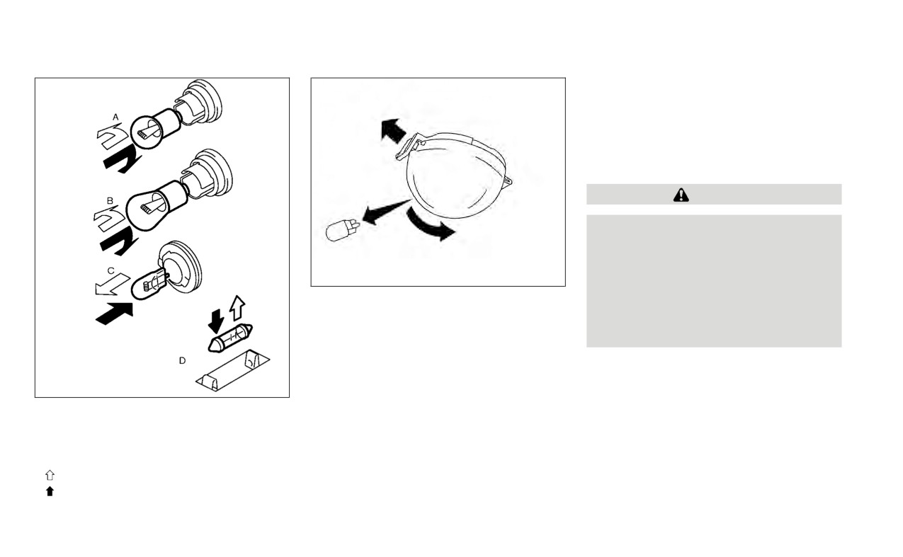
BATTERY REPLACEMENT
CAUTION
Be careful not to allow children to swal-
low the battery or removed parts.
LDI3033
NISSAN JACKKNIFE KEY (if so
2. Replace the battery with a new one.
equipped)
Recommended battery: CR2032
or
equivalent.
To replace the battery:
• Do not touch the internal circuit and elec-
A
tric terminals as doing so could cause a
to open the lid. use a cloth to protect the
malfunction.
casing.
Do-it-yourself
8-21
• Make sure that the + side faces the bot-
For Canada:
B .
This device contains licence-exempt
transmitter(s)/receiver(s) that comply
3. Close lid securely.
with Innovation, Science and Economic
Operate the buttons to check the
Development Canada’s licence-exempt
operation.
RSS(s). Operation is subject to the fol-
lowing two conditions: (1) This device
It is recommended that you visit a NISSAN
may not cause interference. (2) This de-
dealer if you need assistance for
vice must accept any interference, in-
replacement.
cluding interference that may cause un-
FCC Notice:
desired operation of the device.
For USA:
This device complies with Part 15 of the
FCC Rules. Operation is subject to the fol-
lowing two conditions: (1) This device
may not cause harmful interference, and
(2) this device must accept any interfer-
ence received, including interference
that may cause undesired operation.
Note:
Changes or modifications not expressly
approved by the party responsible for
compliance could void the user’s author-
ity to operate the equipment.
LDI2001
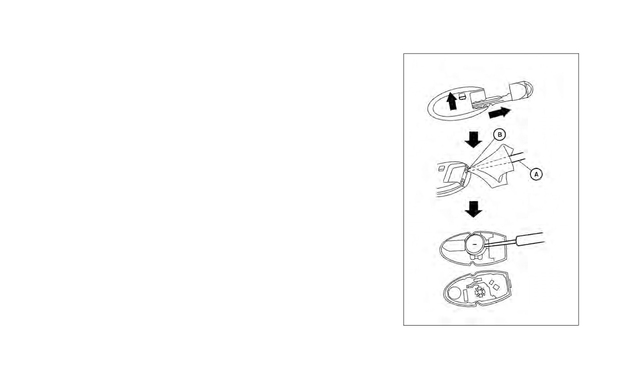
NISSAN INTELLIGENT KEY® (if so
equipped)
8-22
Do-it-yourself

Replace the battery in the Intelligent Key as
3. Replace the battery with a new one.
follows:
Recommended battery: CR2032
or
1.
Remove the mechanical key from the
equivalent.
Intelligent Key.
• Do not touch the internal circuit and elec-
2.
A
tric terminals as doing so could cause a
malfunction.
B of the corner and twist it
to separate the upper part from the
• Hold the battery by the edges. Holding
lower part. Place a cloth over the screw-
the battery across the contact points will
driver to protect the casing.
seriously deplete the storage capacity.
• Make sure that the + side faces the bot-
tom of the lower part.
4. Close the lid securely as illustrated with
D .
5. Operate the buttons to check the
operation.
If you need assistance for replacement, it is
recommended that you visit a NISSAN
dealer for this service.
FCC Notice:
For USA:
This device complies with Part 15 of the
FCC Rules. Operation is subject to the fol-
lowing two conditions: (1) This device
may not cause harmful interference, and
LDI2637
Do-it-yourself
8-23

LIGHTS
(2) this device must accept any interfer-
HEADLIGHTS
• Only touch the base when handling
ence received, including interference
For additional information on headlight
the bulb. Never touch the glass enve-
that may cause undesired operation.
bulb replacement, refer to the instructions
lope. Touching the glass could sig-
Note:
outlined in this section.
nificantly affect bulb life and/or
headlight performance.
Changes or modifications not expressly
Replacing the halogen headlight
• High pressure halogen gas is sealed
approved by the party responsible for
compliance could void the user’s author-
bulb (if so equipped)
inside the halogen bulb. The bulb
may break if the glass envelope is
ity to operate the equipment.
If bulb replacement is required, it is recom-
scratched or the bulb is dropped.
For Canada:
mended that you visit a NISSAN dealer for
• Use the same number and wattage
This device contains licence-exempt
this service.
as shown in the chart.
transmitter(s)/receiver(s) that comply
with Innovation, Science and Economic
CAUTION
Fog may temporarily form inside the
Development Canada’s licence-exempt
lenses of the exterior lights in the rain or in
•
Aiming is not necessary after replac-
RSS(s). Operation is subject to the fol-
a car wash. A temperature difference be-
ing the bulb. When aiming adjust-
lowing two conditions: (1) This device
tween the inside and the outside of the
ment is necessary, it is recom-
may not cause interference. (2) This de-
lens causes the fog. This is not a malfunc-
mended that you visit a NISSAN
vice must accept any interference, in-
tion. If large drops of water collect inside
dealer for this service.
cluding interference that may cause un-
the lens, it is recommended that you visit a
desired operation of the device.
•
Do not leave the headlight assembly
NISSAN dealer for this service.
open without a bulb installed for a
long period of time. Dust, moisture,
Replacing the LED headlight bulb
smoke, etc. entering the headlight
(if so equipped)
body may affect bulb performance.
Remove the bulb from the headlight
If LED headlight bulb replacement is re-
assembly just before a replacement
quired, it is recommended that you visit a
bulb is installed.
NISSAN dealer for this service.
8-24
Do-it-yourself

FOG LIGHTS (if so equipped)
EXTERIOR AND INTERIOR LIGHTS
For additional information on fog light bulb
Item
Wattage (W)
Bulb No.
replacement, refer to the instructions out-
Headlight assembly (Type A) (if so equipped)*
lined in this section.
High
65
H9
Low
55
H11
Turn/Position
28/8
7442NA
Replacing the fog light bulb
Side marker
5
W5W
If fog light bulb replacement is required, it is
Headlight assembly (Type B) (if so equipped)*
High/Low
—
—
recommended that you visit a NISSAN
Position/Daytime running light (if so
dealer for this service.
—
—
equipped)
Turn/Position
28/8
7442NA
CAUTION
Side marker
5
W5W
Fog light (Type A) (if so equipped)*
35
H8
•
High pressure halogen gas is sealed
Fog light assembly (Type B) (if so equipped)*
inside the halogen bulb. The bulb
Fog
35
H8
may break if the glass envelope is
Daytime running light
21
W21W
Door mirror turn signal light (if so equipped)*
—
—
scratched or the bulb is dropped.
Map light*
10
W10W
•
When handling the bulb, do not touch
Room light*
8
—
the glass envelope.
Trunk light
3.4
158
High-mounted stop light*
—
—
•
Use the same number and wattage
Rear combination light*
as originally installed as shown in the
Turn
21
WY21W
chart.
Stop/Tail
21/5
W21/5W
•
Do not leave the bulb out of the fog
Side marker
5
W5W
Backup (reversing) light assembly*
light for a long period of time as dust,
Tail
5
W5W
moisture and smoke may enter the
Backup (reversing)
16
W16W
fog light body and affect the perfor-
License plate light*
5
—
mance of the fog light.
Always check with the Parts Department
at
a NISSAN
dealer
for
the latest
parts
information.
* It is recommended that you visit a NISSAN dealer for replacement.
Do-it-yourself
8-25
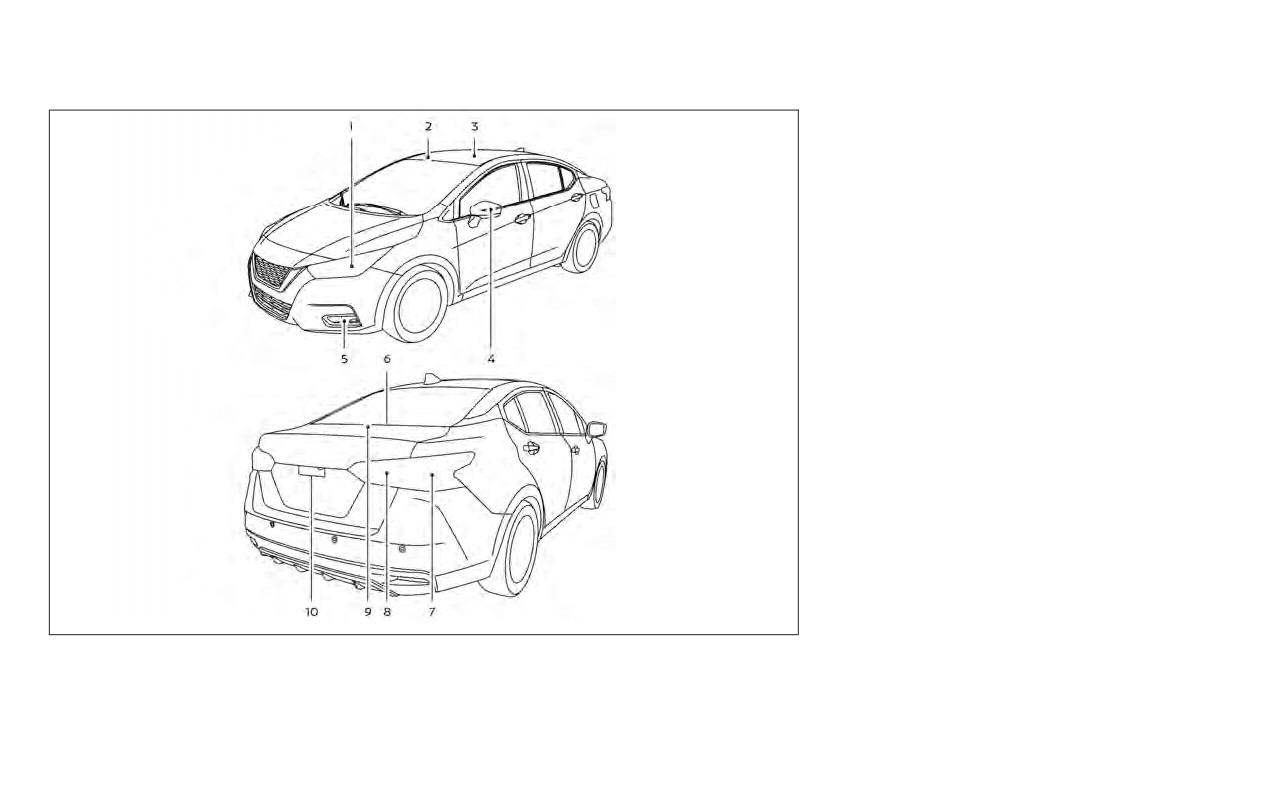
6.
High-mounted stop light
7.
Rear combination light
8.
Backup (reversing) light assembly
9.
Trunk light
10.
License plate light
LDI3441
1.
Headlight assembly
4.
Door mirror turn signal light (if so
2.
Map light
equipped)
3.
Room light
5.
Fog light/Fog light assembly (if so
equipped)
8-26
Do-it-yourself
WHEELS AND TIRES
If you have a flat tire, see “Flat tire”
(P. 6-3).
TIRE PRESSURE
Tire Pressure Monitoring System
(TPMS)
WARNING
Radio waves could adversely af-
fect electric medical equipment.
Those who use a pacemaker
LDI2135
should contact the electric medi-
Trunk light
cal equipment manufacturer for
the possible influences before
use.
This vehicle is equipped with the Tire
Pressure Monitoring System (TPMS).
SDI1805
It monitors tire pressure of all tires
Replacement procedures
except the spare. When the low tire
All other lights are either type A, B, C or D.
pressure warning light is lit and the
When replacing a bulb, first remove the
“Tire Pressure Low - Add Air” warning
lens, lamp and/or cover.
appears in the vehicle information
Indicates bulb removal
display, one or more of your tires is
Indicates bulb installation
significantly under-inflated.
Do-it-yourself
8-27
The TPMS will activate only when the
• Most tires naturally lose air over
Incorrect tire pressure, including
vehicle is driven at speeds above 16
time.
under inflation, may adversely af-
mph (25 km/h). Also, this system
• Tires can lose air suddenly when
fect tire life and vehicle handling.
may not detect a sudden drop in tire
driven over potholes or other ob-
pressure (for example a flat tire while
jects or if the vehicle strikes a curb
driving).
while parking.
For additional information, see “Low
The tire pressures should be
tire pressure warning light” (P. 2-17),
checked when the tires are cold. The
“Tire Pressure Monitoring System
tires are considered COLD after the
(TPMS)” (P. 5-5), and “Flat tire” (P. 6-3).
vehicle has been parked for 3 or
more hours, or driven less than 1 mile
Tire inflation pressure
(1.6 km) at moderate speeds.
Check the tire pressures (including
The TPMS with Easy-Fill Tire Alert
the spare) often and always prior to
provides visual and audible signals
long distance trips. The recom-
outside the vehicle for inflating tires
mended tire pressure specifications
to the recommended COLD tire
are shown on the F.M.V.S.S./C.M.V.S.S.
pressure. For additional information,
certification label or the Tire and
see “TPMS with Easy-Fill Tire Alert”
Loading Information label under the
(P. 5-8).
“Cold Tire Pressure” heading. The Tire
and Loading Information label is af-
fixed to the driver side center pillar.
Tire pressures should be checked
regularly because:
8-28
Do-it-yourself
WARNING
•
Before taking a long trip, or
whenever you heavily load your
•
Improperly inflated tires can
vehicle, use a tire pressure
fail suddenly and cause an
gauge to ensure that the tire
accident.
pressures are at the specified
•
The Gross Vehicle Weight Rat-
level.
ing (GVWR) is located on the
•
For additional information re-
F.M.V.S.S./C.M.V.S.S. certifica-
garding tires, refer to “Impor-
tion label. The vehicle weight
tant Tire Safety Information”
capacity is indicated on the Tire
(US) or “Tire Safety Information”
and Loading Information label.
(Canada) in the Warranty Infor-
Do not load your vehicle be-
mation Booklet.
yond this capacity. Overloading
your vehicle may result in re-
duced tire life, unsafe operating
conditions due to premature
tire failure, or unfavorable han-
dling characteristics and could
also lead to a serious accident.
Loading beyond the specified
capacity may also result in fail-
ure
of
other
vehicle
components.
Do-it-yourself
8-29
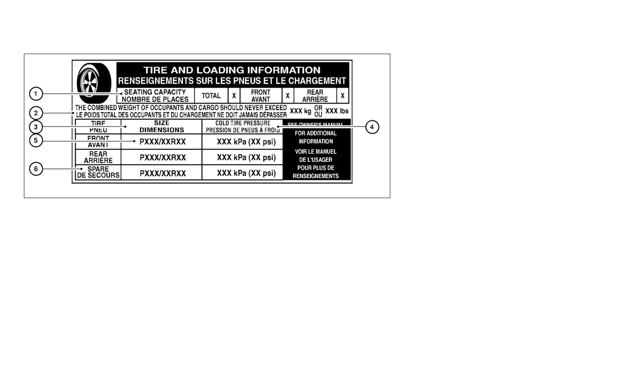
5
Original tire size: The size of the
tires originally installed on the ve-
hicle at the factory.
6
Spare tire size.
LDI2007
Tire and Loading Information
4
Cold tire pressure: Inflate the tires
label
to this pressure when the tires are
1
Seating capacity: The maximum
cold. Tires are considered COLD
number of occupants that can
after the vehicle has been parked
be seated in the vehicle.
for 3 or more hours, or driven less
than 1 mile (1.6 km) at moderate
2
Vehicle load limit: For additional
speeds. The recommended cold
information, see “Vehicle loading
tire inflation is set by the manu-
information” (P. 10-16).
facturer to provide the best bal-
3
Tire size: See
“Tire labeling”
ance of tire wear, vehicle handling,
(P. 8-32).
driveability, tire noise, etc., up to
the vehicle's GVWR.
8-30
Do-it-yourself
3.
Remove the gauge.
Size
Cold Tire Infla-
4.
Read the tire pressure on the
tion Pressure
gauge stem and compare to the
Front and Rear
specification shown on the Tire
Original Tires:
33 PSI, 230 kPa
195/65R15
and Loading Information label.
Front and Rear
5.
Add air to the tire as needed. If too
Original Tires:
33 PSI, 230 kPa
much air is added, press the core
205/55R16
of the valve stem briefly with the
Front and Rear
tip of the gauge stem to release
Original Tires:
33 PSI, 230 kPa
pressure. Recheck the pressure
205/50R17
and add or release air as needed.
LDI0393
Spare Tire:
60 PSI, 420 kPa
Checking tire pressure
6.
Install the valve stem cap.
T125/70D15
1. Remove the valve stem cap from
7.
Check the pressure of all other
the tire.
tires, including the spare.
2. Press the pressure gauge
squarely onto the valve stem. Do
not press too hard or force the
valve stem sideways, or air will es-
cape. If the hissing sound of air
escaping from the tire is heard
while checking the pressure, re-
position the gauge to eliminate
this leakage.
Do-it-yourself
8-31
WDI0394
WDI0395
Example
Example
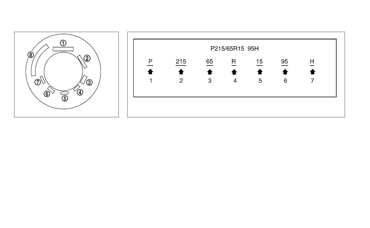
TIRE LABELING
1
Tire size
(example: P215/65R15
3. Two-digit number (65): This num-
95H)
ber, known as the aspect ratio,
Federal law requires tire manufac-
gives the tire's ratio of height to
turers to place standardized infor-
1. P: The “P” indicates the tire is de-
width.
mation on the sidewall of all tires.
signed for passenger vehicles (not
This information identifies and de-
all tires have this information).
4. R: The “R” stands for radial.
scribes the fundamental character-
2. Three-digit number
(215): This
5. Two-digit number (15): This num-
istics of the tire and also provides the
number gives the width in milli-
ber is the wheel or rim diameter in
Tire Identification Number (TIN) for
meters of the tire from sidewall
inches.
safety standard certification. The TIN
edge to sidewall edge.
can be used to identify the tire in
case of a recall.
8-32
Do-it-yourself

6. Two- or three-digit number (95):
This number is the tire's load in-
dex. It is a measurement of how
much weight each tire can
support.
7. H: Tire speed rating. You should
not drive the vehicle faster than
the tire speed rating.
LDI2786
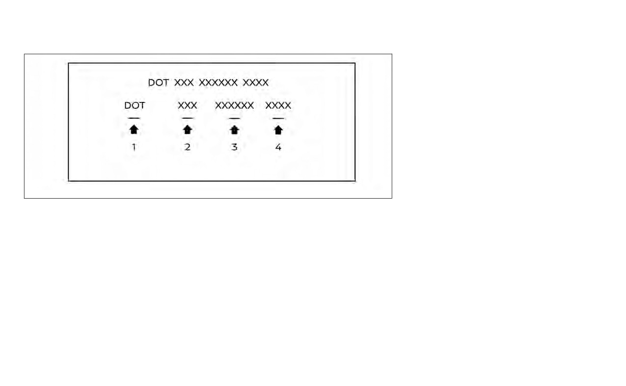
Example (Type A) (if so equipped)
2
TIN (Tire Identification Number)
3. Two-digit code: Tire size.
for a new tire (example: DOT XX XX
4. Three-digit code: Tire type code
XXX XXXX)
(Optional).
1. DOT: Abbreviation for the “Depart-
5. Four numbers represent the
ment Of Transportation”. The
week and year the tire was built.
symbol can be placed above, be-
For example, the numbers 3103
low or to the left or right of the Tire
means the 31st week of 2003. If
Identification Number.
these numbers are missing then
2. Two-digit code: Manufacturer's
look on the other sidewall of the
identification mark.
tire.
Do-it-yourself
8-33
manufacturers also must indicate
the materials in the tire, which include
steel, nylon, polyester and others.
4
Maximum permissible inflation
pressure
This number is the greatest amount
of air pressure that should be put in
the tire. Do not exceed the maximum
permissible inflation pressure.
5
Maximum load rating
LDI3639
This number indicates the maximum
Example (Type B) (if so equipped)
load in kilograms and pounds that
2
TIN (Tire Identification Number)
3. Six-digit code: Descriptive code
can be carried by the tire. When re-
for a new tire (example: DOT XXX
used to identify significant char-
placing the tires on the vehicle, always
XXXXXX XXXX)
acteristics of the tire.
use a tire that has the same load rat-
1. DOT: Abbreviation for the “Depart-
4. Four numbers represent the
ing as the factory installed tire.
ment Of Transportation”. The
week and year the tire was built.
6
Term of “tubeless” or “tube type”
symbol can be placed above, be-
For example, the numbers 3103
Indicates whether the tire requires
low or to the left of the Tire Identi-
means the 31st week of 2003.
an inner tube (“tube type”) or not
fication Number.
3
Tire ply composition and material
(“tubeless”).
2. Three-digit code: Manufacturer's
The number of layers or plies of
identification mark.
rubber-coated fabric in the tire. Tire
8-34
Do-it-yourself

7
The word “radial”
TYPES OF TIRES
• Always use tires of the same type,
WARNING
size, brand, construction and tread
The word “radial” is shown if the tire
pattern on all four wheels. Failure to
has radial structure.
•
When changing or replacing tires, be
do so may result in a circumference
sure all four tires are of the same type
difference between tires on the front
8
Manufacturer or brand name
(i.e., Summer, All Season or Snow)
and rear axles which can cause the
Manufacturer or brand name is
and construction. A NISSAN dealer
Vehicle Dynamic Control (VDC) sys-
may be able to help you with infor-
tem to malfunction resulting in per-
shown.
mation about tire type, size, speed
sonal injury or death, excessive tire
rating and availability.
wear and may damage the transmis-
Other Tire-related Terminology
•
Replacement tires may have a lower
sion and differential gears.
In addition to the many terms that
speed rating than the factory
• For additional information regarding
are defined throughout this section,
equipped tires, and may not match
tires, refer to “Important Tire Safety
the potential maximum vehicle
Information” (US) or “Tire Safety In-
Intended Outboard Sidewall is (1) the
speed. Never exceed the maximum
formation” (Canada) in the Warranty
sidewall that contains a whitewall,
speed rating of the tire.
Information Booklet.
bears white lettering or bears
•
Replacing tires with those not origi-
manufacturer, brand, and/or model
nally specified by NISSAN could af-
All season tires
fect the proper operation of the low
name molding that is higher or
NISSAN specifies All Season tires on some
tire pressure warning system.
deeper than the same molding on
models to provide good performance all
year, including snowy and icy road condi-
the other sidewall of the tire, or (2)
tions. All Season tires are identified by ALL
the outward facing sidewall of an
SEASON and/or M&S on the tire sidewall.
asymmetrical tire that has a particu-
Snow tires have better snow traction than
lar side that must always face out-
All Season tires and may be more appropri-
ate in some areas.
ward when mounted on a vehicle.
Do-it-yourself
8-35
Summer tires
states and Canadian provinces prohibit
to the fenders or underbody. If possible,
their use. Check local, state and provincial
avoid fully loading your vehicle when using
NISSAN specifies summer tires on some
laws before installing studded tires. Skid
tire chains. In addition, drive at a reduced
models to provide superior performance
and traction capabilities of studded snow
speed. Otherwise, your vehicle may be
on dry roads. Summer tire performance is
tires on wet or dry surfaces may be poorer
damaged and/or vehicle handling and
substantially reduced in snow and ice.
than that of non-studded snow tires.
performance may be adversely affected.
Summer tires do not have the tire traction
rating “M&S” on the tire sidewall.
Tire chains must be installed only on the
TIRE CHAINS
front wheels and not on the rear wheels.
If you plan to operate your vehicle in snowy
Use of tire chains may be prohibited ac-
or icy conditions, NISSAN recommends the
Never install tire chains on a TEMPORARY
cording to location. Check the local laws
use of SNOW tires or ALL SEASON tires on all
USE ONLY spare tire.
before installing tire chains. When installing
four wheels.
tire chains, make sure they are the proper
Do not use tire chains on dry roads. Driving
size for the tires on your vehicle and are
with chains in such conditions can cause
Snow tires
installed according to the chain manufac-
damage to the various mechanisms of the
If snow tires are needed, it is necessary to
turer's suggestions. Use only SAE class “S”
vehicle due to some overstress.
select tires equivalent in size and load rat-
chains. Class “S” chains are used on ve-
hicles with restricted tire to vehicle clear-
NOTE:
ing to the original equipment tires. If you do
ance. Vehicles that can use Class “S” chains
not, it can adversely affect the safety and
Tire chains are not
permitted for
use
handling of your vehicle.
are designed to meet the minimum clear-
with 17 in wheels.
ances between the tire and the closest ve-
Generally, snow tires have lower speed rat-
hicle suspension or body component re-
ings than factory equipped tires and may
quired to accommodate the use of a
not match the potential maximum vehicle
winter traction device
(tire chains or
speed. Never exceed the maximum speed
cables). The minimum clearances are de-
rating of the tire.
termined using the factory equipped tires.
If you install snow tires, they must be the
Other types may damage your vehicle. Use
same size, brand, construction and tread
chain tensioners when recommended by
pattern on all four wheels.
the tire chain manufacturer to ensure a
tight fit. Loose end links of the tire chain
For additional traction on icy roads, stud-
must be secured or removed to prevent
ded tires may be used. However, some U.S.
the possibility of whipping action damage
8-36
Do-it-yourself
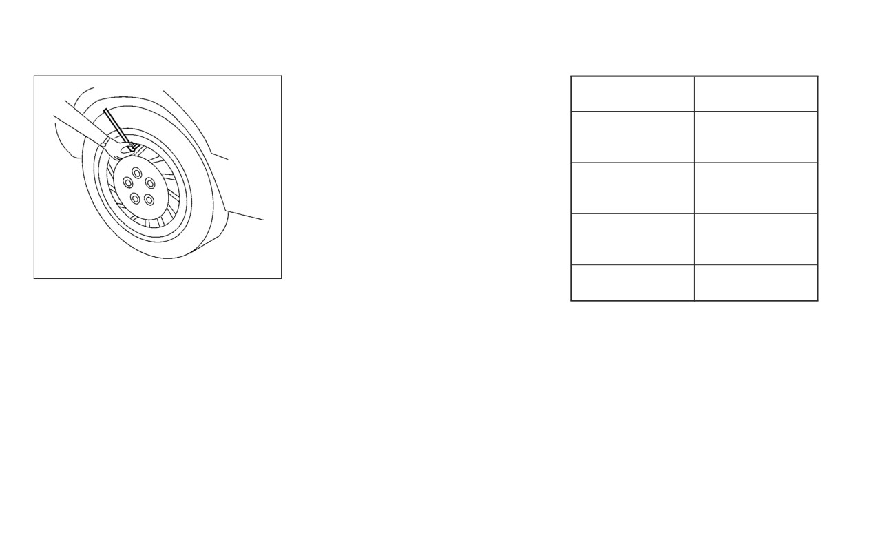
Wheel nut tightening torque:
83 ft-lb (113 N·m)
The wheel nuts must be kept tight-
ened to specifications at all times.
It is recommended that wheel nuts
be tightened to specification at
each tire rotation interval.
WARNING
•
After rotating the tires, check
WDI0258
and adjust the tire pressure.
WDI0259
CHANGING WHEELS AND TIRES
•
Retighten the wheel nuts when
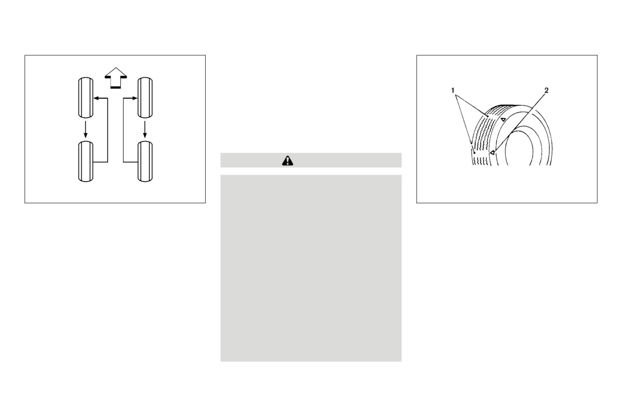
Tire wear and damage
the vehicle has been driven for
Tire rotation
1. Wear indicator
600 miles (1,000 km) (also in
NISSAN recommends rotating the
2. Location mark
cases of a flat tire, etc.).
tires every 7,500 miles (12,000 km).
•
Do not include the spare tire in
For additional information on tire re-
the tire rotation.
placing procedures, see
“Flat tire”
•
For additional information re-
(P. 6-3).
garding tires, refer to “Impor-
As soon as possible, tighten the
tant Tire Safety Information”
wheel nuts to the specified torque
(US) or “Tire Safety Informa-
with a torque wrench.
tion” (Canada) in the Warranty
Information Booklet.
Do-it-yourself
8-37