Nissan Rogue (2020 year). Manual - part 13


  Index      Nissan     Nissan Rogue (2020 year) - manual in english


Search            copyright infringement  


Content      ..     11      12      13      14     ..


Nissan Rogue (2020 year). Manual - part 13


2. Insert a suitable tool in the lower ac-

cess opening hole. Move the release
lever to the right. The liftgate will be
unlatched.

3. Push the liftgate up to open.

NOTE:

If you had to open the liftgate using this
lever, it is recommended that you have
your vehicle checked as soon as pos-
sible. It is recommended that you visit a
NISSAN dealer for this service.

Power liftgate release (if so
equipped)

The liftgate release mechanism allows the
liftgate to be opened in the event of a dis-
charged battery.

To release the liftgate from the inside of the
vehicle, perform the following operations:

1. Fold the rear seats down. For additional

information, refer to “Folding the rear
bench seat” in the “Safety—Seats, seat
belts and supplemental restraint sys-
tem” section of this manual.

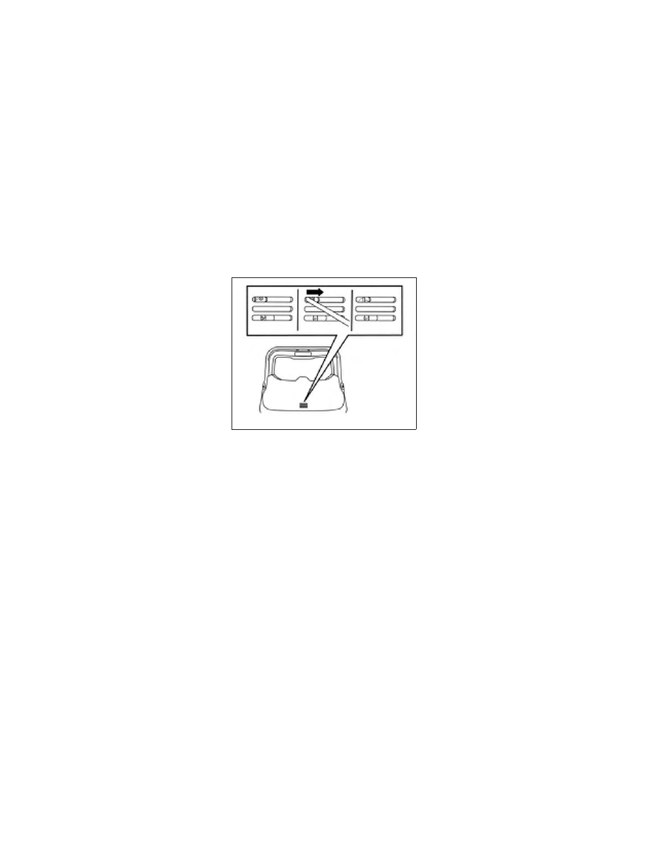
2. Insert a suitable tool in the top access

opening hole. Move the release lever to
the right. The liftgate will be unlatched.

3. Push the liftgate up to open.

NOTE:

If you had to open the liftgate using this
lever, it is recommended that you have
your vehicle checked as soon as pos-
sible. It is recommended that you visit a
NISSAN dealer for this service.

LPD2949

3-32

Pre-driving checks and adjustments

-------------------------------------------------------------------------------------------------------------------------------------------------------------

LIFTGATE POSITION SETTING (if so
equipped)

The liftgate can be set to open to a specific
height by performing the following:

1. Open the liftgate using the request

switch or the Intelligent Key.

2. Pull the liftgate down to the desired

position and hold the liftgate (the lift-
gate will have some resistance when
being manually adjusted).

3. While holding the liftgate in position,

push and hold the liftgate switch

B

located on the liftgate for approxi-
mately 5 seconds or until two beeps
are heard.

The liftgate will open to the selected posi-
tion setting. To change the position of the
liftgate, repeat steps 1-3 for setting the po-
sition of the liftgate.

OPENER OPERATION

The fuel-filler door opener switch is located
on the instrument panel. To open, push the
fuel-filler opener switch.

To lock, close the fuel-filler door securely.

LPD2615

LPD3030

FUEL-FILLER DOOR

Pre-driving checks and adjustments

3-33

-------------------------------------------------------------------------------------------------------------------------------------------------------------

FUEL-FILLER CAP

WARNING

∙ Gasoline is extremely flammable and

highly explosive under certain condi-
tions. You could be burned or seri-
ously injured if it is misused or mis-
handled. Always stop the engine and
do not smoke or allow open flames or
sparks

near

the

vehicle

when

refueling.

∙ Do not attempt to top off the fuel tank

after the fuel pump nozzle shuts off
automatically.

Continued

refueling

may cause fuel overflow, resulting in
fuel spray and possibly a fire.

∙ Use only an original equipment type

fuel-filler cap as a replacement. It has
a built-in safety valve needed for
proper operation of the fuel system
and emission control system. An in-
correct cap can result in a serious mal-
function and possible injury. It could
also cause the

Malfunction Indi-

cator Light (MIL) to come on.

∙ Never pour fuel into the throttle body

to attempt to start your vehicle.

∙ Do not fill a portable fuel container in

the vehicle or trailer. Static electricity
can cause an explosion of flammable
liquid, vapor or gas in any vehicle or
trailer. To reduce the risk of serious
injury or death when filling portable
fuel containers:

– Always place the container on the

ground when filling.

– Do not use electronic devices when

filling.

– Keep the pump nozzle in contact

with the container while you are
filling it.

– Use only approved portable fuel

containers for flammable liquid.

CAUTION

∙ Do not use a fuel containing more

than 15% ethanol in your vehicle. For
additional information, refer to “Fuel
recommendation” in the “Technical
and consumer information” section of
this manual.

∙ The Loose Fuel Cap warning message

will be displayed/warning will appear
if the fuel-filler cap is not properly
tightened. It may take a few driving
trips for the message to be displayed.
Failure to tighten the fuel-filler cap
properly after the Loose Fuel Cap
warning

message

is

displayed/warning

appears

may

cause the

Malfunction Indicator

Light (MIL) to illuminate.

∙ Failure to tighten the fuel-filler cap

properly may cause the

Mal-

function Indicator Light (MIL) to illumi-
nate. If the

light illuminates be-

cause the fuel-filler cap is loose or
missing, tighten or install the cap and
continue

to

drive

the

vehicle.

The

light should turn off after a

few driving trips. If the

light does

not turn off after a few driving trips,
have the vehicle inspected. It is rec-
ommended that you visit a NISSAN
dealer for this service.

∙ For additional information, refer to

“Malfunction Indicator Light (MIL)” in
the “Instruments and controls” sec-
tion of this manual.

3-34

Pre-driving checks and adjustments

-------------------------------------------------------------------------------------------------------------------------------------------------------------

∙ If fuel is spilled on the vehicle body,

flush it away with water to avoid paint
damage.

NOTE:

Changing ignition switch status during
the refueling process may cause a delay
in fuel gauge response.

To remove the fuel-filler cap:

1. Turn the fuel-filler cap counterclock-

wise to remove.

2. Put the fuel-filler cap on the cap holder

1

while refueling.

To install the fuel-filler cap:

1. Insert the fuel-filler cap straight into the

fuel-filler tube.

2. Turn the fuel-filler cap clockwise until a

single click is heard.

Loose Fuel Cap warning

The Loose Fuel Cap warning message will
be displayed in the vehicle information dis-
play when the fuel-filler cap is not tight-
ened correctly after the vehicle has been
refueled. It may take a few driving trips for
the message to be displayed. To turn off
the warning message, perform the follow-
ing:

1. Remove and install the fuel-filler cap as

soon as possible. For additional infor-
mation, refer to “Fuel-filler cap” in this
section.

LPD2186

LPD3016

Pre-driving checks and adjustments

3-35

-------------------------------------------------------------------------------------------------------------------------------------------------------------

2. Tighten the fuel-filler cap until a single

click is heard.

3. Press the OK button on the steering

wheel for about one second to turn off
the Loose Fuel Cap warning message
after tightening the fuel-filler cap.

WARNING

∙ Do not adjust the steering wheel while

driving. You could lose control of your
vehicle and cause an accident.

∙ Do not adjust the steering wheel any

closer to you than is necessary for
proper steering operation and com-
fort. The driver’s air bag inflates with
great force. If you are unrestrained,
leaning forward, sitting sideways or
out of position in any way, you are at
greater risk of injury or death in a
crash. You may also receive serious or
fatal injuries from the air bag if you
are up against it when it inflates. Al-
ways sit back against the seatback
and as far away as practical from the
steering wheel. Always use the seat
belts.

MANUAL OPERATION

Tilt and telescopic operation

Pull the lock lever

1

down:

∙ Adjust the steering wheel up or down in

direction

2

to the desired position.

∙ Adjust the steering wheel forward or

backward in direction

3

to the desired

position.

Push the lock lever

1

up firmly to lock the

steering wheel in place.

LPD2648

STEERING WHEEL

3-36

Pre-driving checks and adjustments

-------------------------------------------------------------------------------------------------------------------------------------------------------------

1. To block glare from the front, swing

down the sun visor

1

.

2. To block glare from the side, remove

the sun visor from the center mount
and swing the visor to the side

2

.

3. To extend the sun visor, slide

3

in or

out as needed.

CAUTION

∙ Do not store the sun visor before re-

turning the extension to its original
position.

∙ Do not pull the extension sun visor

forcedly downward.

VANITY MIRRORS

To access the vanity mirror, pull the sun
visor down and flip open the mirror cover.
Some vanity mirrors will illuminate when
the mirror cover is open.

WPD0344

LPD2067

SUN VISORS

Pre-driving checks and adjustments

3-37

-------------------------------------------------------------------------------------------------------------------------------------------------------------

CARD HOLDER

To access the card holder, slide card in the
card holder. Do not view information while
operating the vehicle.

MANUAL ANTI-GLARE REARVIEW
MIRROR (if so equipped)

Use the night position

1

to reduce glare

from the headlights of vehicles behind you
at night.

Use the day position

2

when driving in

daylight hours.

WARNING

Use the night position only when neces-
sary, because it reduces rear view
clarity.

AUTOMATIC ANTI-GLARE
REARVIEW MIRROR (if so equipped)

The inside mirror is designed so that it au-
tomatically dims during night time condi-
tions and according to the intensity of the
headlights of the vehicle following you. The
automatic anti-glare feature is activated
when the ignition switch is in the ON posi-
tion.

NOTE:

Do not hang any objects over the sen-
sors

1

or apply glass cleaner to the sen-

sors. Doing so will reduce the sensitivity
of the sensors, resulting in improper op-
eration.

Driver’s side

LPD2598

WPD0126

MIRRORS

3-38

Pre-driving checks and adjustments

-------------------------------------------------------------------------------------------------------------------------------------------------------------

Type A (if so equipped)

The inside mirror is designed so that it au-
tomatically dims during night time condi-
tions and according to the intensity of the
headlights of the vehicle following you. The
automatic anti-glare feature is activated
when the ignition switch is in the ON posi-
tion.

Type B and Type C (if so equipped)

The indicator light

2

will illuminate when the

automatic anti-glare feature is operating.

To turn off the automatic anti-glare feature,
press:

∙ The O

button for inside mirrors with-

out compass, and the indicator light will
turn off.

∙ The

button for inside mirrors

with compass, and the indicator light
will turn off.

To turn on the automatic anti-glare feature,
press:

∙ The I

button for inside mirrors with-

out compass, and the indicator light will
turn on.

∙ The

button for inside mirrors

with compass, and the indicator light
will turn on.

For additional information on HomeLink®
Universal Transceiver operation, refer to
the “HomeLink® Universal Transceiver” in
the “Instruments and controls” section of
this manual.

Type A (if so equipped)

LPD2418

Type B— Without compass (if so equipped)

LPD0469

Type C— With compass (if so equipped)

LPD2419

Pre-driving checks and adjustments

3-39

-------------------------------------------------------------------------------------------------------------------------------------------------------------

For information on the compass display

3

(if so equipped), refer to “Compass display”
in the “Instruments and controls” section of
this manual.

OUTSIDE MIRRORS

The outside mirror remote control will op-
erate only when the ignition switch is in the
ON position.

Move the small switch

1

to select the left

or right mirror. Adjust each mirror to the
desired position using the large switch

2

.

Move the switch

1

to the center (neutral)

position to prevent accidentally moving
the mirror.

WARNING

∙ Objects viewed in the outside mirror

on the passenger side are closer than
they appear. Be careful when moving
to the right. Using only this mirror
could cause an accident. Use the in-
side mirror or glance over your shoul-
der to properly judge distances to
other objects.

∙ Do not adjust the mirrors while driv-

ing. You could lose control of your ve-
hicle and cause an accident.

LPD2452

3-40

Pre-driving checks and adjustments

-------------------------------------------------------------------------------------------------------------------------------------------------------------

Manual folding outside mirrors

Pull the outside mirror toward the door to
fold it.

Reverse tilt-down feature (if so
equipped)

The reverse tilt-down feature will turn both
outside mirror surfaces downward to pro-
vide better rear visibility close to the vehicle
when the mirror control switch is in either
the L or R position.

The mirrors automatically return to their
original position when you shift out of R
(Reverse).

The outside mirror surfaces will return to
their original position when one of the fol-
lowing conditions has occurred:

∙ The shift lever is moved to any position

other than R (Reverse).

∙ The outside mirror control switch is set

to the neutral or center position.

∙ The ignition switch is placed in the OFF

position.

NOTE:

If the outside mirror control switch is in
the “center” position, the mirror surface
will NOT turn downward when the shift
lever is moved to R (Reverse).

For additional information, refer to “Auto-
matic drive positioner” in this section.

Heated mirrors (if so equipped)

Some outside mirrors can be heated to
defrost, defog, or de-ice for improved vis-
ibility. For additional information, refer to
“Rear window and outside mirror (if so
equipped) defroster switch” in the “Instru-
ments and controls” section of this manual.

The automatic drive positioner system has
two features:

∙ Memory storage function

∙ Entry/exit function

LPD2084

AUTOMATIC DRIVE POSITIONER (if so
equipped)

Pre-driving checks and adjustments

3-41

-------------------------------------------------------------------------------------------------------------------------------------------------------------

MEMORY STORAGE FUNCTION

Two positions for the driver’s seat and out-
side mirrors can be stored in the automatic
drive positioner memory. Follow these pro-
cedures to use the memory system.

NOTE:

The vehicle should be stopped while set-
ting the memory.

1. Adjust the driver’s seat and outside mir-

rors to the desired positions by manu-
ally operating each adjusting switch.
For additional information, refer to
“Seats” in the “Safety—Seats, seat belts

and supplemental restraint system”
section of this manual and “Outside
mirrors” in this section.

2. Push the SET switch and, within 5 sec-

onds, push the memory switch (1 or 2).
The indicator light for the pushed
memory switch will come on and stay
on for approximately 5 seconds.

The chime will sound when the memory is
stored.

NOTE:

If a new memory position is stored in the
same memory switch, the previous
memory position will be overwritten by
the new stored position.

Confirming memory storage

∙ Push the SET switch.

∙ If a memory position has not been

stored in the switch (1 or 2) the indicator
light for the respective switch will come
ON for approximately 0.5 seconds.

∙ If a memory position has been stored in

the switch (1 or 2) then the indicator light
for the respective switch will stay ON for
approximately 5 seconds.

Linking a key fob to a stored
memory position

Each key fob can be linked to a stored
memory position (memory switch 1 or 2)
with the following procedure.

1. Follow steps 1 and 2 in the “Memory

storage function” section for storing
the memory position.

2. While the indicator light is on, press

the

button on the key fob. The

indicator light of the linked memory
switch will blink. After the indicator light
goes off, the key fob is linked to that
memory setting.

Once it is linked, when ignition switch is
placed

in

the

OFF

position, pressing

the

button on the key fob will move

the driver’s seat and outside mirrors to the
linked memory switch position.

NOTE:

If a new memory position is stored in the
linked memory switch, then the key fob
will link the new position and overwrites
the previous position.

LPD2531

3-42

Pre-driving checks and adjustments

-------------------------------------------------------------------------------------------------------------------------------------------------------------

ENTRY/EXIT FUNCTION

This system is designed so that the driver’s
seat will automatically move when the shift
lever is in the P (Park) position. This allows
the driver to easily get in and out of the
seat.

The driver’s seat will slide backward when
the ignition is switched to OFF and the driv-
er’s door is opened.

The driver’s seat will return to the previous
position when the ignition is switched to
ON.

The entry/exit function can be enabled or
disabled through “Vehicle Settings” in the
vehicle information display by performing
the following:

∙ Switch the “Exit Seat Slide” from ON to

OFF. For additional information, refer to
“Vehicle information display” in the “In-
struments and controls” section of this
manual.

SYSTEM OPERATION

The automatic drive positioner system will
not work or will stop operating under the
following conditions:

∙ When the vehicle speed is above 4 mph

(7 km/h).

∙ When any of the memory switches are

pushed while the automatic drive posi-
tioner is operating.

∙ When the switch for the driver’s seat

and steering column is pushed while
the automatic drive positioner is oper-
ating.

∙ When the seat has already been moved

to the memorized position.

∙ When no seat position is stored in the

memory switch.

∙ When the shift lever is moved from P

(Park) to any other position.

Pre-driving checks and adjustments

3-43

-------------------------------------------------------------------------------------------------------------------------------------------------------------

4 Monitor, climate, audio, phone and
voice recognition systems

NissanConnect® Owner’s Manual . . . . . . . . . . . . . . . . 4-2
RearView Monitor (if so equipped) . . . . . . . . . . . . . . . 4-3

RearView Monitor system operation . . . . . . . . . . 4-4
How to read the displayed lines. . . . . . . . . . . . . . . 4-5
Difference between predicted and
actual distances. . . . . . . . . . . . . . . . . . . . . . . . . . . . . . 4-5
How to park with predicted course
lines . . . . . . . . . . . . . . . . . . . . . . . . . . . . . . . . . . . . . . . . . . 4-7
Adjusting the screen . . . . . . . . . . . . . . . . . . . . . . . . . 4-8
How to turn on and off predicted
course lines . . . . . . . . . . . . . . . . . . . . . . . . . . . . . . . . . . 4-9
RearView Monitor system limitations . . . . . . . . . 4-9
System maintenance. . . . . . . . . . . . . . . . . . . . . . . . 4-10

Intelligent Around View Monitor
(if so equipped) . . . . . . . . . . . . . . . . . . . . . . . . . . . . . . . . . .4-11

Intelligent Around View Monitor system
operation. . . . . . . . . . . . . . . . . . . . . . . . . . . . . . . . . . . . 4-12
Difference between predicted and
actual distances. . . . . . . . . . . . . . . . . . . . . . . . . . . . . 4-16
How to park with predicted course
lines . . . . . . . . . . . . . . . . . . . . . . . . . . . . . . . . . . . . . . . . . 4-18
How to switch the display . . . . . . . . . . . . . . . . . . . 4-19
Adjusting the screen . . . . . . . . . . . . . . . . . . . . . . . . 4-20

Intelligent Around View Monitor system
limitations . . . . . . . . . . . . . . . . . . . . . . . . . . . . . . . . . . . 4-20
System maintenance. . . . . . . . . . . . . . . . . . . . . . . . 4-22

Moving Object Detection (MOD)
(if so equipped) . . . . . . . . . . . . . . . . . . . . . . . . . . . . . . . . . 4-23

MOD system operation . . . . . . . . . . . . . . . . . . . . . . 4-24
Turning MOD on and off (if so equipped) . . . . . 4-26
MOD system limitations . . . . . . . . . . . . . . . . . . . . . 4-26
System maintenance. . . . . . . . . . . . . . . . . . . . . . . . 4-27

Vents. . . . . . . . . . . . . . . . . . . . . . . . . . . . . . . . . . . . . . . . . . . 4-28
Heater and air conditioner (manual)
(if so equipped) . . . . . . . . . . . . . . . . . . . . . . . . . . . . . . . . . 4-29

Controls . . . . . . . . . . . . . . . . . . . . . . . . . . . . . . . . . . . . . 4-30
Heater operation . . . . . . . . . . . . . . . . . . . . . . . . . . . . 4-30
Air conditioner operation . . . . . . . . . . . . . . . . . . . . 4-32
Air flow charts . . . . . . . . . . . . . . . . . . . . . . . . . . . . . . . 4-33

Heater and air conditioner (automatic)
(if so equipped) . . . . . . . . . . . . . . . . . . . . . . . . . . . . . . . . . 4-37

Automatic operation . . . . . . . . . . . . . . . . . . . . . . . . 4-38
Manual operation . . . . . . . . . . . . . . . . . . . . . . . . . . . 4-39
Operating tips . . . . . . . . . . . . . . . . . . . . . . . . . . . . . . . 4-40

Servicing air conditioner . . . . . . . . . . . . . . . . . . . . . . . . 4-41
USB/iPod® charging port . . . . . . . . . . . . . . . . . . . . . . . 4-42

-------------------------------------------------------------------------------------------------------------------------------------------------------------

-------------------------------------------------------------------------------------------------------------------------------------------------------------

Refer to the NissanConnect® Owner’s
Manual that includes the following infor-
mation.

∙ NissanConnect®

Services

(if

so

equipped)

∙ Navigation system (if so equipped)

∙ Audio system

∙ Apple CarPlay®

∙ Android Auto

TM

∙ Bluetooth® Hands-Free Phone system

∙ Viewing information

∙ Other settings

∙ Voice recognition

∙ General system information

NISSANCONNECT® OWNER’S
MANUAL

4-2

Monitor, climate, audio, phone and voice recognition systems

-------------------------------------------------------------------------------------------------------------------------------------------------------------

1. CAMERA button

LHA4694

REARVIEW MONITOR (if so
equipped)

Monitor, climate, audio, phone and voice recognition systems

4-3

-------------------------------------------------------------------------------------------------------------------------------------------------------------


Content      ..     11      12      13      14     ..