Nissan Rogue Sport (2018 year). Instruction - part 28
8-18
Do-it-yourself
occasional brake squeak, squeal or other
noise may be heard. Occasional brake
noise during light to moderate stops is
normal and does not affect the function
or performance of the brake system.
Proper brake inspection intervals
should be followed. For additional infor-
mation, see the maintenance schedule
shown in the “9. Maintenance and sche-
dules” section.
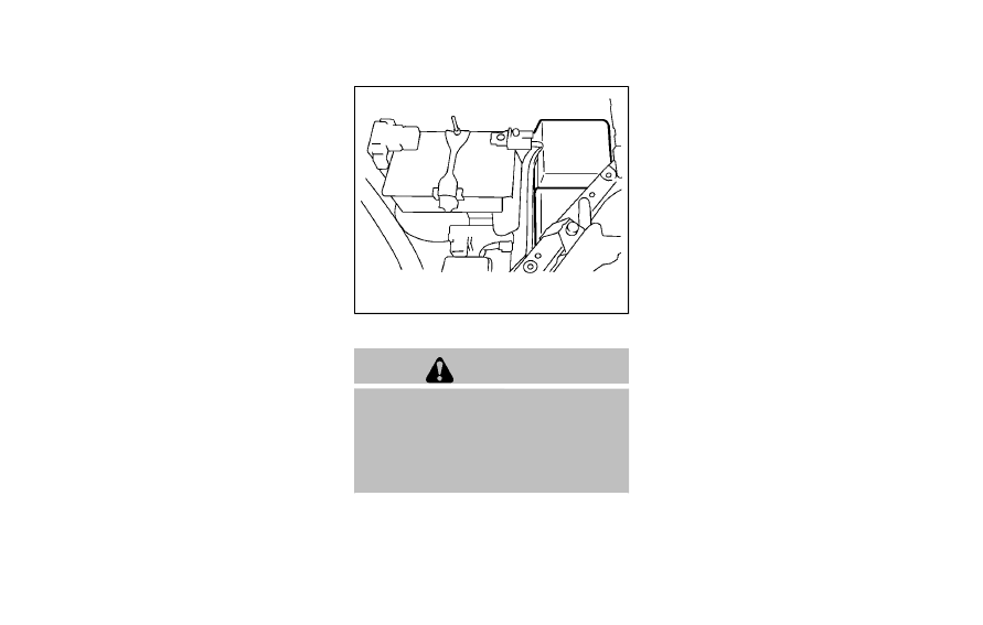
JVM0386X
ENGINE COMPARTMENT
WARNING
Never use a fuse of a higher or lower
amperage rating than that specified
on the fuse box cover. This could
damage the electrical system or
electronic control units or cause a
fire.
If any electrical equipment does not
operate, check for an open fuse.
1.
Be sure the ignition switch and the
headlight switch are turned off.
2. Open the engine hood.
3. Remove the fuse/fusible link box cov-
er by using a suitable tool and pushing
the tab.
4. Locate the fuse that needs to be
replaced.
5. Remove the fuse using the fuse puller
located in the passenger compart-
ment fuse box.
FUSES