Nissan Rogue Sport (2018 year). Instruction - part 5
1-56
Safety — Seats, seat belts and supplemental restraint system
electrical equipment. Unauthor-
ized electrical test equipment
and probing devices should not
be used on the pretensioner sys-
tem.
. If you need to dispose of a pre-
tensioner or scrap the vehicle, it is
recommended you visit a NISSAN
dealer for this service. Correct
pretensioner disposal procedures
are set forth in the appropriate
NISSAN Service Manual. Incorrect
disposal procedures could cause
personal injury.
The pretensioner system may activate
with the supplemental air bag system in
certain types of collisions. Working with
the seat belt retractor, it helps tighten the
seat belt when the vehicle becomes
involved in certain types of collisions,
helping to restrain front seat occupants.
The pretensioner is encased with the seat
belt retractor. These seat belts are used
the same way as conventional seat belts.
When a pretensioner activates, smoke is
released and a loud noise may be heard.
The smoke is not harmful and does not
indicate a fire. Care should be taken not
to inhale it, as it may cause irritation and
choking. Those with a history of a breath-
ing condition should get fresh air
promptly.
After pretensioner activation, load limiters
allow the seat belt to release webbing (if
necessary) to reduce forces against the
chest.
The supplemental air bag warning light
is used to indicate malfunctions in
the pretensioner system. See “Supple-
mental air bag warning light” (P.1-57). If
the operation of the supplemental air bag
warning light indicates there is a mal-
function, have the system checked. It is
recommended you visit a NISSAN dealer
for this service.
When selling your vehicle, we request that
you inform the buyer about the preten-
sioner system and guide the buyer to the
appropriate sections in this Owner’s Man-
ual.
SSS1020
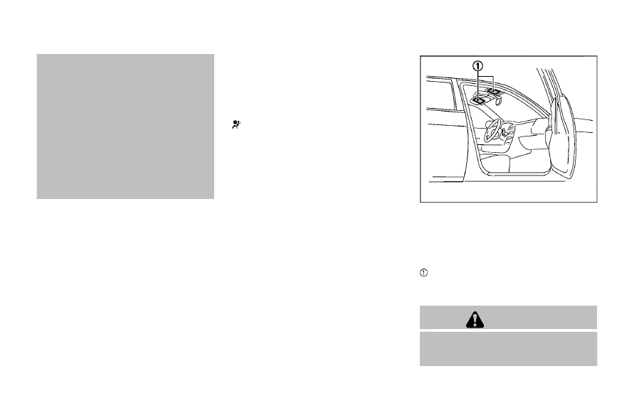
SUPPLEMENTAL AIR BAG WARNING
LABELS
Warning labels about the supplemental
front-impact air bag system are placed in
the vehicle as shown in the illustration.
SRS air bag
The warning labels are located on the
surface of the sun visors.
WARNING
Do not use a rear-facing child re-
straint on a seat protected by an air
bag in front of it. If the air bag