Nissan Quest (2017 year). Instruction - part 25
5-18
Starting and driving
SSD1030
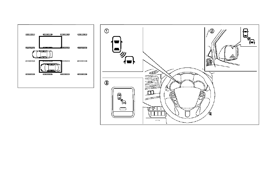
Detection zone
The radar sensors can detect vehicles on either
side of your vehicle within the detection zone
shown as illustrated. This detection zone starts
from the outside mirror of your vehicle and
extends approximately 10 ft (3.0 m) behind the
rear bumper, and approximately 10 ft (3.0 m)
sideways.
JVS0724X
*
1
BSW system warning light
*
2
Side indicator light
*
3
BSW switch