Nissan Frontier D40. Manual - part 965
SEC-16
< COMPONENT DIAGNOSIS >
U1000 CAN COMM CIRCUIT
COMPONENT DIAGNOSIS
U1000 CAN COMM CIRCUIT
Description
INFOID:0000000005272589
CAN (Controller Area Network) is a serial communication line for real time applications. It is an on-vehicle mul-
tiplex communication line with high data communication speed and excellent error detection ability. Modern
vehicle is equipped with many electronic control unit, and each control unit shares information and links with
other control units during operation (not independent). In CAN communication, control units are connected
with 2 communication lines (CAN-H line, CAN-L line) allowing a high rate of information transmission with less
wiring. Each control unit transmits/receives data but selectively reads required data only.
CAN Communication Signal Chart, refer to
LAN-48, "CAN Communication Signal Chart"
DTC Logic
INFOID:0000000005272590
DTC DETECTION LOGIC
Diagnosis Procedure
INFOID:0000000005272591
1.
PERFORM SELF DIAGNOSTIC
1.
Turn ignition switch ON and wait for 2 seconds or more.
2.
Check “Self Diagnostic Result”.
Is “CAN COMM CIRCUIT” displayed?
YES
>> Refer to
LAN-5, "CAN Communication Control Circuit"
.
NO
>> Refer to
GI-46, "Intermittent Incident"
.
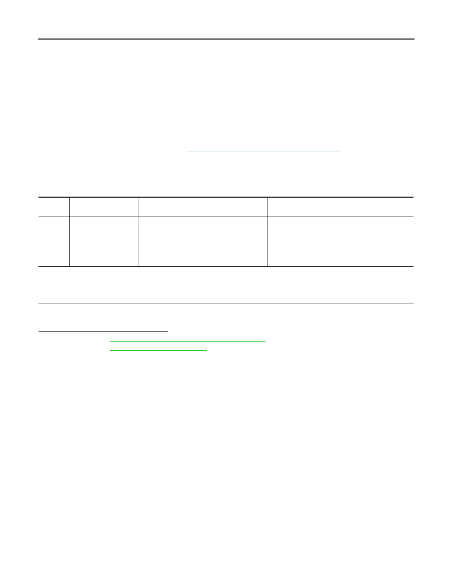
DTC
CONSULT-III display
description
DTC Detection Condition
Possible cause
U1000
CAN COMM CIRCUIT
When BCM cannot communicate CAN com-
munication signal continuously for 2 sec-
onds or more.
In CAN communication system, any item (or items)
of the following listed below is malfunctioning.
• Receiving (TCM)
• Receiving (IPDM E/R)
• Receiving (ECM)
• Receiving (METER/M&A)