Nissan Frontier D40. Manual - part 855
MWI
DIAGNOSIS SYSTEM (METER)
MWI-25
< FUNCTION DIAGNOSIS >
C
D
E
F
G
H
I
J
K
L
M
B
A
O
P
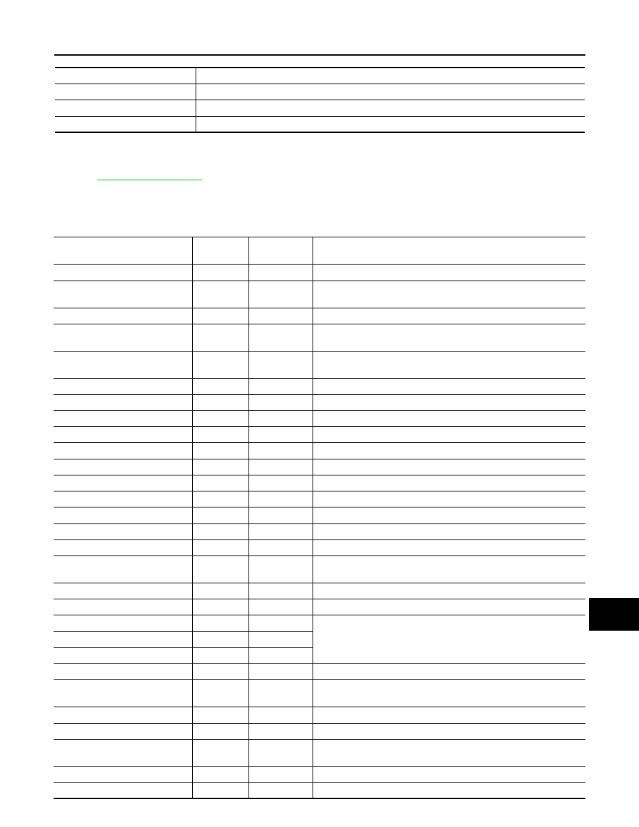
SELF-DIAG RESULTS
Display Item List
.
DATA MONITOR
Display Item List
X: Applicable
METER/M&A diagnosis mode
Description
SELF-DIAG RESULTS
Displays combination meter self-diagnosis results.
DATA MONITOR
Displays combination meter input/output data in real time.
CAN DIAG SUPPORT MNTR
The result of transmit/receive diagnosis of CAN communication can be read.
Display item [Unit]
MAIN
SIGNALS
SELECTION
FROM MENU
Description
SPEED METER [km/h] or [mph]
X
X
Displays the value of vehicle speed signal.
SPEED OUTPUT [km/h] or [mph]
X
X
Displays the value of vehicle speed signal, which is transmitted to
each unit with CAN communication.
TACHO METER [rpm]
X
X
Displays the value of engine speed signal, which is input from ECM.
FUEL METER [lit.]
X
X
Displays the value, which processes a resistance signal from fuel
gauge.
W TEMP METER [
°
C] or [
°
F]
X
X
Displays the value of engine coolant temperature signal, which is in-
put from ECM.
ABS W/L [ON/OFF]
X
Displays [ON/OFF] condition of ABS warning lamp.
VDC/TCS IND [ON/OFF]
X
Displays [ON/OFF] condition of VDC OFF indicator lamp.
SLIP IND [ON/OFF]
X
Displays [ON/OFF] condition of SLIP indicator lamp.
BRAKE W/L [ON/OFF]
X
Displays [ON/OFF] condition of brake warning lamp.*
DOOR W/L [ON/OFF]
X
Displays [ON/OFF] condition of door warning lamp.
HI-BEAM IND [ON/OFF]
X
Displays [ON/OFF] condition of high beam indicator.
TURN IND [ON/OFF]
X
Displays [ON/OFF] condition of turn indicator.
OIL W/L [ON/OFF]
X
Displays [ON/OFF] condition of oil pressure warning lamp.
C-ENG W/L [ON/OFF]
X
Displays [ON/OFF] condition of malfunction indicator lamp.
CRUISE IND [ON/OFF]
X
Displays [ON/OFF] condition of CRUISE indicator.
SET IND [ON/OFF]
X
Displays [ON/OFF] condition of SET indicator.
O/D OFF W/L [ON/OFF]
X
Displays [ON/OFF] condition of AT CHECK (with manual mode) or
O/D OFF (without manual mode) warning lamp.
FUEL W/L [ON/OFF]
X
X
Displays [ON/OFF] condition of low-fuel warning lamp.
AIR PRES W/L [ON/OFF]
X
Displays [ON/OFF] condition of tire pressure warning lamp.
KEY G/Y W/L [ON/OFF]
X
This item is not used for this model. “OFF” is always displayed.
KEY R W/L [ON/OFF]
X
KEY KNOB W/L [ON/OFF]
X
M RANGE SW [ON/OFF]
X
X
Displays [ON/OFF] condition of manual mode range switch.
NM RANGE SW [ON/OFF]
X
X
Displays [ON/OFF] condition of except for manual mode range
switch.
AT SFT UP SW [ON/OFF]
X
X
Displays [ON/OFF] condition of A/T shift-up switch.
AT SFT DWN SW [ON/OFF]
X
X
Displays [ON/OFF] condition of A/T shift-down switch.
DISTANCE [km] or [mile]
X
X
Displays the value, which is calculated by vehicle speed signal, fuel
gauge and fuel consumption from ECM.
BUZZER [ON/OFF]
X
X
Displays [ON/OFF] condition of buzzer.
BRAKE SW [ON/OFF]
X
Indicates [ON/OFF] condition of parking brake switch.