Nissan Frontier D40. Manual - part 808


  Index      Nissan     Nissan Frontier D40 (2010 year) - Service and Repair Manual


Search            


Content   ..  806  807  808  809   ..


Nissan Frontier D40. Manual - part 808


LAN

DIAGNOSIS AND REPAIR WORKFLOW

LAN-19

< BASIC INSPECTION >

[CAN FUNDAMENTAL]

C

D

E

F

G

H

I

J

K

L

B

A

O

P

N

Some items may not be needed depending on CAN system type of vehicle.

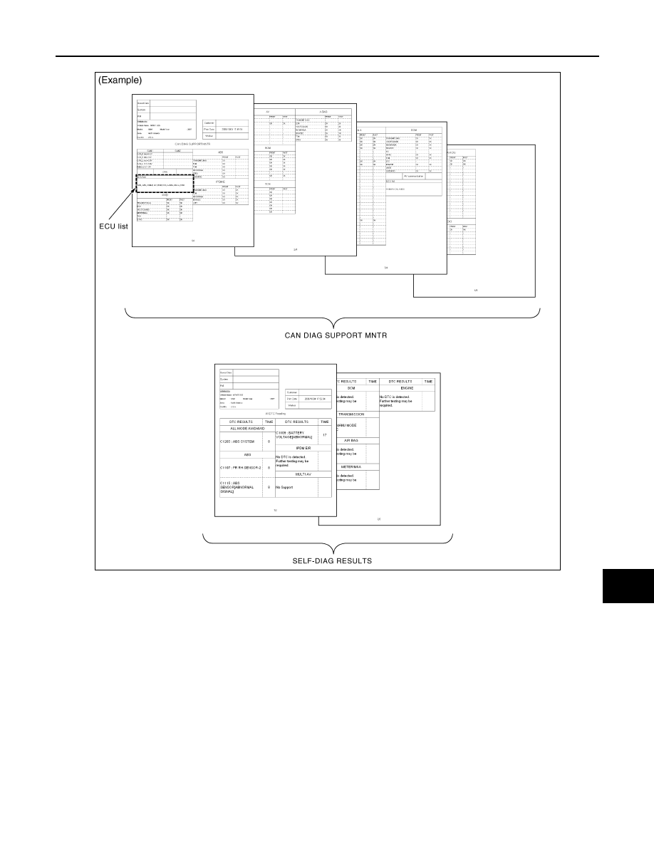
Create On-board Diagnosis Copy Sheet

Display the trouble diagnosis result of CAN communication with the on-board diagnosis function on the vehicle
monitor, etc. Copy them on the on-board diagnosis copy sheet.
NOTE:

PKID1212E

LAN-20

< BASIC INSPECTION >

[CAN FUNDAMENTAL]

DIAGNOSIS AND REPAIR WORKFLOW

For some models, CAN communication diagnosis result is received from the vehicle monitor. (CONSULT-III is
not available.)

CREATE DIAGNOSIS SHEET

NOTE:
Be sure to use the diagnosis sheet for the correct CAN system type.

Print Diagnosis Sheet

Print the diagnosis sheet for the applicable CAN system type.

Check Collected Data

Make sure that all ECUs are received, referring to “ECU list”.

SKIB8722E

LAN

DIAGNOSIS AND REPAIR WORKFLOW

LAN-21

< BASIC INSPECTION >

[CAN FUNDAMENTAL]

C

D

E

F

G

H

I

J

K

L

B

A

O

P

N

• For abbreviations, refer to 

LAN-36, "Abbreviation List"

.

DETECT THE ROOT CAUSE

Identify the root cause using the created diagnosis sheet.

Identifying the root cause

• Draw a line on the diagnosis sheet to indicate the possible cause. Narrow the search.

NOTE:
• Color-code when drawing lines.
• Do not draw a line onto a existing line.

• Drawing a line is not necessary if the circuit is shorted. Refer to “Present Error — Short Circuit —”, “Past

Error — Short Circuit —”.

Refer to the following for details of the trouble diagnosis procedure.
• “Present Error — Open Circuit —”
• “Present Error — Short Circuit —”
• “Past Error — Open Circuit —”
• “Past Error — Short Circuit —”
NOTE:
When the root cause appears to be a branch line or short circuit, be sure to check the control unit as well as
the communication line.

Present Error — Open Circuit —

PKID1213E

LAN-22

< BASIC INSPECTION >

[CAN FUNDAMENTAL]

DIAGNOSIS AND REPAIR WORKFLOW

Identify the error circuit using information from the “CAN DIAG SUPPORT MNTR” (“ECU list” included).

1.

ECU list: Check the items indicated in “ECU list”. Draw a line on the diagnosis sheet to indicate the error
circuit.
NOTE:
CAN communication line has no error if units other than Diag on CAN units are not indicated. An error
may be on the power supply of the control unit, DDL1 line or DDL2 line.

a.

“TCM” which is Diag on CAN unit, is not indicated on “ECU list”. This indicates that DLC is not receiving a
signal from TCM. Draw a line to indicate an error between DLC and TCM (line 1-a in the figure below).
NOTE:
• Diag on CAN units are not indicated on the “ECU list” when the CAN line between Diag on CAN unit and

the data link connector is open.

• For a description of Diag on CAN, refer to 

LAN-6, "Description"

.

2.

CAN DIAG SUPPORT MNTR: Check each item on “CAN DIAG SUPPORT MNTR”. Draw a line on the
diagnosis sheet to indicate the error circuit.

a.

Reception item of “ECM”: On “TCM”, “UNKWN” is indicated. This means ECM cannot receive the signal
from TCM. Draw a line to indicate an error between ECM and TCM (line 2-a in the figure below).
NOTE:
If “UNKWN” is indicated on “TRANSMIT DIAG”, then the control unit cannot transmit CAN communication
signal to each unit. Draw a line between the control unit and the splice.

b.

Reception item of “AFS”: On “TCM”, “UNKWN” is indicated. This means AFS cannot receive the signal
from TCM. Draw a line to indicate an error between AFS and TCM (line 2-b in the figure below).

PKID1214E


Content   ..  806  807  808  809   ..