Nissan Frontier D40. Manual - part 746
MANUAL A/C IDENTIFICATION TABLE
HAC-87
< COMPONENT DIAGNOSIS >
[MANUAL A/C (TYPE 2)]
C
D
E
F
G
H
J
K
L
M
A
B
HAC
N
O
P
COMPONENT DIAGNOSIS
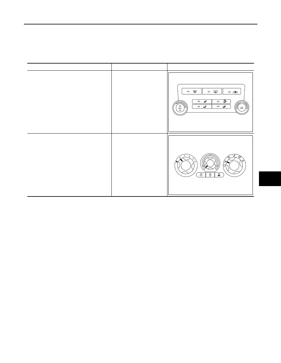
MANUAL A/C IDENTIFICATION TABLE
Application Table
INFOID:0000000005275924
Manual A/C Type
Description
Visual Identification
Manual A/C (Type 1)
Two Control Dial System
[with variable blower control
(VBC)]
Manual A/C (Type 2)
Three Control Dial System
[without variable blower con-
trol (VBC)]
AWIIA0481ZZ
AWIIA1228ZZ