Nissan Frontier D40. Manual - part 734
MAGNET CLUTCH
HAC-39
< COMPONENT DIAGNOSIS >
[MANUAL A/C (TYPE 1)]
C
D
E
F
G
H
J
K
L
M
A
B
HAC
N
O
P
•
WITHOUT CONSULT-III
GO TO 8.
NO
>> Check 10A fuse (No. 42, located in IPDM E/R), and GO TO 12.
2.
CHECK BCM INPUT (A/C COMPRESSOR ON) SIGNAL
Check A/C compressor ON/OFF signal. Refer to
HAC-15, "CONSULT-III Function (BCM - AIR CONDI-
.
Is the inspection result normal?
YES
>> GO TO 3.
NO
>> GO TO 8.
3.
CHECK REFRIGERANT PRESSURE SENSOR
Check refrigerant pressure sensor. Refer to
(QR25DE) or
(VQ40DE).
Is the inspection result normal?
YES
>> GO TO 4.
NO
>> Replace refrigerant pressure sensor. Refer to
HA-38, "Removal and Installation for Refrigerant
4.
CHECK BCM INPUT (FAN ON) SIGNAL
Check FAN ON/OFF signal. Refer to
BCS-21, "AIR CONDITIONER : CONSULT-III Function (BCM - AIR CON-
Is the inspection result normal?
YES
>> GO TO 7.
NO
>> GO TO 5.
5.
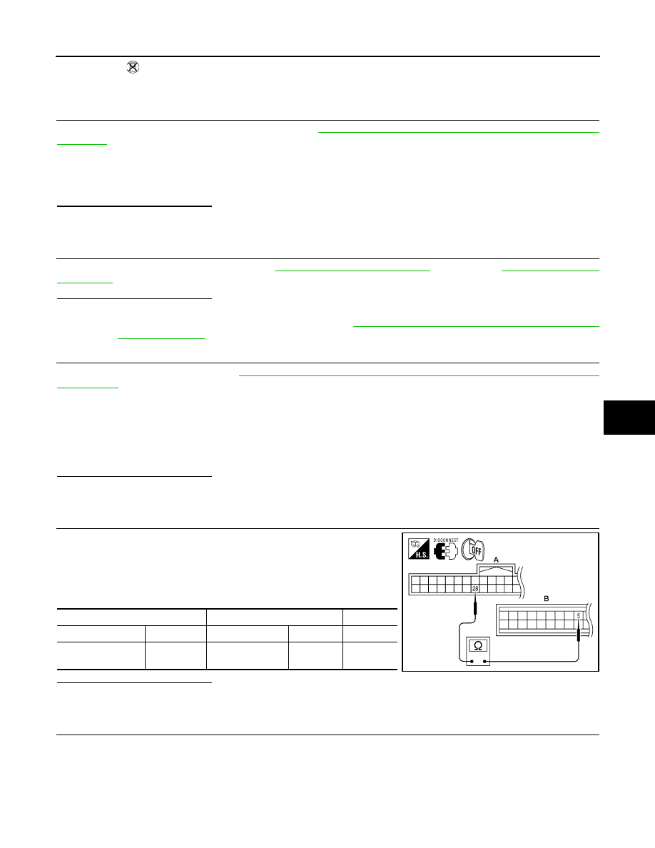
CHECK CIRCUIT CONTINUITY BETWEEN BCM AND FRONT AIR CONTROL
1.
Turn ignition switch OFF.
2.
Disconnect BCM connector and front air control connector.
3.
Check continuity between BCM harness connector M18 (A) ter-
minal 28 and front air control harness connector M50 (B) termi-
nal 5.
Is the inspection result normal?
YES
>> GO TO 6.
NO
>> Repair harness or connector.
6.
CHECK VOLTAGE FOR FRONT AIR CONTROL (FAN ON SIGNAL)
A/C SW ON
: AIR COND SW ON
A/C SW OFF
: AIR COND SW OFF
BLOWER CONTROL DIAL
ON
: FAN ON SIG ON
BLOWER CONTROL DIAL
OFF
: FAN ON SIG OFF
A
B
Connector
Terminal Connector
Terminal
Continuity
BCM: M18
28
Front air control:
M50
5
Yes
AWIIA0418ZZ