Nissan Frontier D40. Manual - part 733


  Index      Nissan     Nissan Frontier D40 (2010 year) - Service and Repair Manual


Search            


Content   ..  731  732  733  734   ..


Nissan Frontier D40. Manual - part 733


BLOWER MOTOR

HAC-35

< COMPONENT DIAGNOSIS >

[MANUAL A/C (TYPE 1)]

C

D

E

F

G

H

J

K

L

M

A

B

HAC

N

O

P

8.

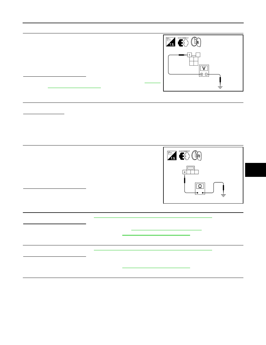
CHECK FRONT BLOWER MOTOR RELAY (COIL SIDE) POWER SUPPLY

1.

Turn ignition switch ON.

2.

Check voltage between front blower motor relay harness con-
nector terminal 1 and ground.

• E54 (King Cab)
• E55 (Crew Cab)

Is the inspection result normal?

YES

>> Replace variable blower control. Refer to 

VTL-10,

"Removal and Installation"

.

NO

>> Repair front blower motor ground circuit or connector.

9.

REPLACE FUSES

Replace fuses.

Does the fuse blow?

YES

>> • If fuse blows without activating the front blower motor, repair short between fuse and front

blower motor relay. 

• If fuse blows activating the front blower motor, GO TO 10. 

NO

>> Inspection End.

10.

CHECK FRONT BLOWER MOTOR POWER SUPPLY CIRCUIT FOR SHORT

1.

Turn ignition switch OFF.

2.

Disconnect front blower motor connector and variable blower
control connector.

3.

Check continuity between variable blower control harness con-
nector M121 terminal 4 and ground.

Is the inspection result normal?

YES

>> GO TO 11.

NO

>> Repair harness or connector.

11.

CHECK FRONT BLOWER MOTOR

Check front blower motor. Refer to 

HAC-32, "Front Blower Motor Component Function Check"

.

Is the inspection result normal?

YES

>> Replace variable blower control. Refer to 

VTL-10, "Removal and Installation"

.

NO

>> Replace front blower motor. Refer to 

VTL-9, "Removal and Installation"

.

12.

CHECK FRONT BLOWER MOTOR

Check front blower motor. Refer to 

HAC-32, "Front Blower Motor Component Function Check"

.

Is the inspection result normal?

YES

>> GO TO 13.

NO

>> Replace front blower motor. Refer to 

VTL-9, "Removal and Installation"

.

13.

CHECK BLOWER MOTOR GROUND CIRCUIT

1 - Ground

: Battery voltage

WJIA1991E

4 - Ground

: Continuity should not exist.

AWIIA0177ZZ

HAC-36

< COMPONENT DIAGNOSIS >

[MANUAL A/C (TYPE 1)]

BLOWER MOTOR

1.

Disconnect variable blower control harness connector.

2.

Check continuity between front blower motor harness connector
M62 (B) terminal 1 and variable blower control harness connec-
tor M121 (A) terminal 2.

Is the inspection result normal?

YES

>> GO TO 14.

NO

>> Repair harness or connector.

14.

CHECK VARIABLE BLOWER CONTROL POWER SUPPLY CIRCUIT FOR OPEN

Check continuity between front blower motor relay harness connec-
tor (A) terminals 3, 6 and variable blower control harness connector
M121 (B) terminal 4.
• E54 (King Cab)
• E55 (Crew Cab)

Is the inspection result normal?

YES

>> GO TO 15.

NO

>> Repair harness or connector.

15.

CHECK VARIABLE BLOWER CONTROL GROUND CIRCUIT

Check continuity between variable blower control harness connector
M121 terminal 1 and ground.

Is the inspection result normal?

YES

>> GO TO 16. 

NO

>> Repair harness or connector.

16.

CHECK VARIABLE BLOWER CONTROL SIGNAL CIRCUIT

1.

Reconnect all disconnected component connectors.

2.

Disconnect front air control connector.

3.

Turn ignition switch ON.

4.

Turn blower control dial to maximum speed.

5.

check voltage between front air control harness connector M50
terminal 24 and ground.

Is the inspection result normal?

YES

>> Replace front air control. Refer to 

VTL-7, "Removal and

Installation"

.

NO

>> GO TO 17.

17.

CHECK VARIABLE BLOWER CONTROL SIGNAL CIRCUIT

1 - 2

: Continuity should exist.

AWIIA0179ZZ

3, 6 - 4

: Continuity should exist.

AWIIA1212ZZ

1 - Ground

: Continuity should exist.

AWIIA0180ZZ

24 - Ground

Approx.: 4.5V

AWIIA1226ZZ

BLOWER MOTOR

HAC-37

< COMPONENT DIAGNOSIS >

[MANUAL A/C (TYPE 1)]

C

D

E

F

G

H

J

K

L

M

A

B

HAC

N

O

P

1.

Turn ignition switch OFF.

2.

Disconnect variable blower control.

3.

Check continuity between front air control harness connector
M50 (B) terminal 24 and variable blower control harness con-
nector M121 (A) terminal 3.

Is the inspection result normal?

YES

>> Replace variable blower control. Refer to 

VTL-10,

"Removal and Installation"

.

NO

>> Repair harness or connector.

Front Blower Motor Component Inspection

INFOID:0000000005275887

COMPONENT INSPECTION 

Front Blower Motor Relay

Check continuity between terminals 3 and 5 and terminals 7 and 6
by supplying 12 volts and ground to coil side terminals 1 and 2 of the
relay.

Front Blower Motor

Confirm smooth rotation of the blower motor.
• Ensure that there are no foreign particles inside the blower unit.
• Apply 12 volts to terminal 2 and ground to terminal 1 and verify that

the motor operates freely and quietly.

24 - 3

: Continuity should exist.

AWIIA1213ZZ

LJIA0068E

WJIA1508E

HAC-38

< COMPONENT DIAGNOSIS >

[MANUAL A/C (TYPE 1)]

MAGNET CLUTCH

MAGNET CLUTCH

System Description

INFOID:0000000005275888

SYSTEM DESCRIPTION

The front air control controls compressor operation based on intake temperature and a signal from ECM.

Low Temperature Protection Control

The front air control will turn the compressor ON or OFF as determined by a signal detected by the intake sen-
sor.
When intake air temperature is higher than 3.5

°

C (38.3

°

F), the compressor turns ON. The compressor turns

OFF when intake air temperature is lower than 2.5

°

C (36.5

°

F).

Magnet Clutch Component Function Check

INFOID:0000000005275889

SYMPTOM: Magnet clutch does not engage.

INSPECTION FLOW

1.

CONFIRM SYMPTOM BY PERFORMING OPERATIONAL CHECK - MAGNET CLUTCH

1.

Rotate blower control dial clockwise. 

2.

Press the vent (

) mode switch.

3.

Press A/C switch. Confirm that the compressor clutch engages (sound or visual inspection). 

Is the inspection result normal?

YES

>> Inspection End.

NO

>> Go to diagnosis procedure. Refer to 

HAC-38, "Magnet Clutch Diagnosis Procedure"

.

Magnet Clutch Diagnosis Procedure

INFOID:0000000005275890

Regarding Wiring Diagram information, refer to 

HAC-50, "Wiring Diagram - Air Conditioner Control - With

VBC"

.

DIAGNOSTIC PROCEDURE FOR MAGNET CLUTCH

SYMPTOM: Magnet clutch does not engage when A/C switch is ON.

1.

PERFORM IPDM E/R AUTO ACTIVE TEST

Perform IPDM E/R auto active test. Refer t

PCS-15, "CONSULT - III Function (IPDM E/R)"

.

Does magnet clutch operate?

YES

>> •

WITH CONSULT-III

GO TO 2.

AWIIA1216GB


Content   ..  731  732  733  734   ..