Nissan Frontier D40. Manual - part 730
MODE DOOR MOTOR
HAC-23
< COMPONENT DIAGNOSIS >
[MANUAL A/C (TYPE 1)]
C
D
E
F
G
H
J
K
L
M
A
B
HAC
N
O
P
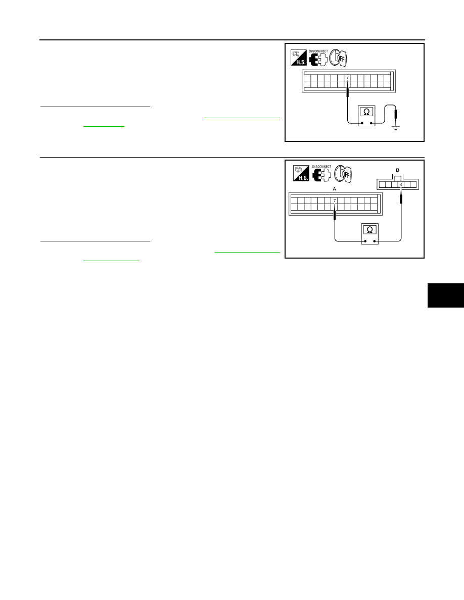
1.
Turn ignition switch OFF.
2.
Disconnect front air control harness connector.
3.
Check continuity between front air control harness connector
M50 terminal 7 and ground.
Is the inspection result normal?
YES
>> Replace front air control. Refer to
NO
>> Repair or replace harness as necessary.
12.
CHECK PBR FEEDBACK CIRCUIT FOR OPEN
1.
Turn ignition switch OFF.
2.
Disconnect the mode door motor harness connector and front
air control harness connector.
3.
Check continuity between mode door motor harness connector
M142 (B) terminal 4 and front air control harness connector M50
(A) terminal 7.
Is the inspection result normal?
YES
>> Replace mode door motor. Refer to
.
NO
>> Repair or replace harness as necessary.
Continuity should not exist.
AWIIA0370ZZ
Continuity should exist.
AWIIA1205ZZ