Nissan Frontier D40. Manual - part 729


  Index      Nissan     Nissan Frontier D40 (2010 year) - Service and Repair Manual


Search            


Content   ..  727  728  729  730   ..


Nissan Frontier D40. Manual - part 729


MODE DOOR MOTOR

HAC-19

< COMPONENT DIAGNOSIS >

[MANUAL A/C (TYPE 1)]

C

D

E

F

G

H

J

K

L

M

A

B

HAC

N

O

P

MODE DOOR MOTOR

System Description

INFOID:0000000005275875

SYSTEM DESCRIPTION

Component Parts

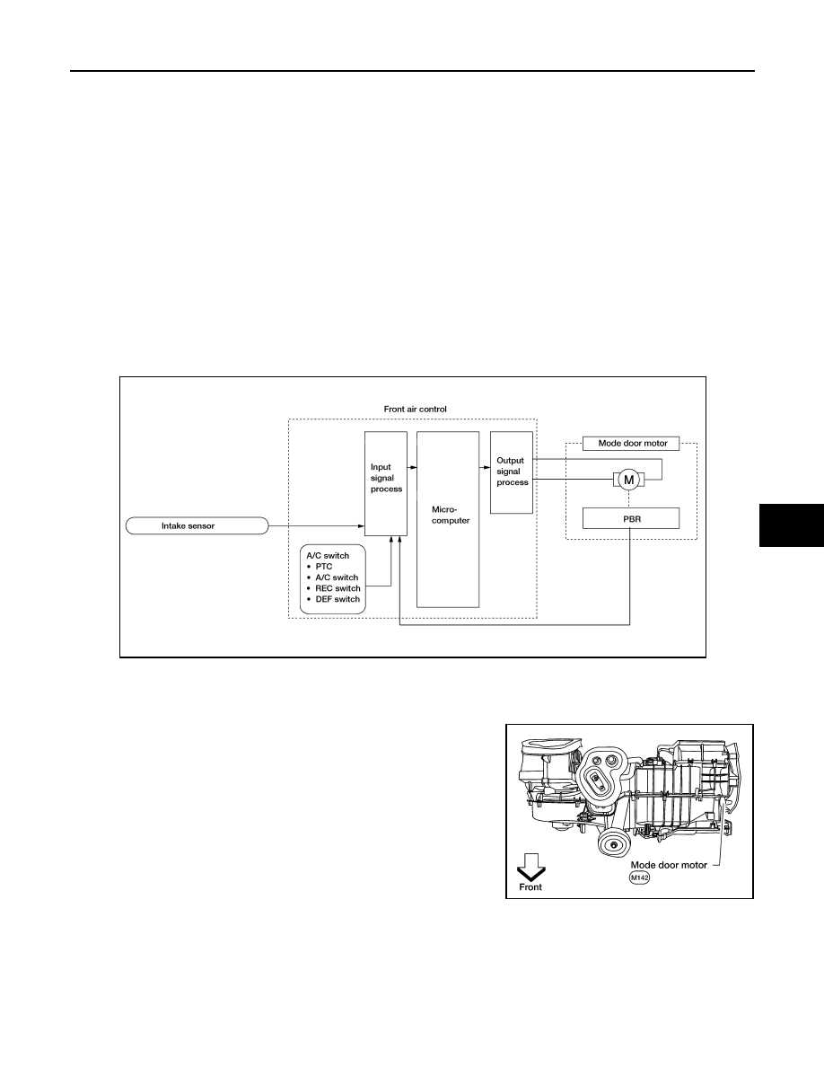
Mode door control system components are:

• Front air control
• Mode door motor
• PBR (built into mode door motor)
• Intake sensor

System Operation

The mode door position (vent, B/L, foot, D/F, and defrost) is set by the front air control by means of the mode
door motor. When a mode door position is selected on the front air control, voltage is applied to one circuit of
the mode door motor while ground is applied to the other circuit, causing the mode door motor to rotate. The
direction of rotation is determined by which circuit has voltage applied to it, and which one has ground applied
to it. The front air control monitors the mode door position by measuring the voltage signal on the PBR circuit.

COMPONENT DESCRIPTION

Mode Door Motor

The mode door motor is attached to the heater and cooling unit
assembly. It rotates so that air is discharged from the outlet as indi-
cated by the front air control. Motor rotation is conveyed to a link
which activates the mode door.

Mode Door Motor Component Function Check

INFOID:0000000005275876

SYMPTOM:

• Air outlet does not change.
• Mode door motor does not operate normally.

INSPECTION FLOW

WJIA1314E

WJIA1484E

HAC-20

< COMPONENT DIAGNOSIS >

[MANUAL A/C (TYPE 1)]

MODE DOOR MOTOR

1.

CONFIRM SYMPTOM BY PERFORMING OPERATIONAL CHECK - DISCHARGE AIR

1.

Turn blower control dial to HI speed. 

2.

Press each mode switch and check all positions. 

3.

Confirm that discharge air comes out according to the air distribution table. Refer to 

HAC-12, "Discharge

Air Flow"

.

NOTE:
Confirm that the compressor clutch is engaged (visual inspection) and intake door position is at FRESH
when DEF (

) or D/F (

) is selected.

Is the inspection result normal?

YES

>> Inspection End.

NO

>> Go to diagnosis procedure. Refer to 

HAC-20, "Mode Door Motor Diagnosis Procedure"

.

Mode Door Motor Diagnosis Procedure

INFOID:0000000005275877

Regarding Wiring Diagram information, refer to 

HAC-50, "Wiring Diagram - Air Conditioner Control - With

VBC"

.

SYMPTOM:

• Air outlet does not change.
• Mode door motor does not operate normally.

1.

CHECK FRONT AIR CONTROL FOR POWER AND GROUND 

1.

Turn ignition switch ON.

2.

Press the B/L (

) mode switch.

3.

Check voltage between front air control harness connector M50
terminal 19 and terminal 20 while pressing the mode switch to
the floor (

) mode.

Is the inspection result normal?

YES

>> GO TO 3.

NO

>> GO TO 2.

2.

CHECK MODE DOOR MOTOR CIRCUITS FOR SHORT TO GROUND 

1.

Turn ignition switch OFF.

2.

Disconnect the front air control harness connector.

3.

Check continuity between front air control harness connector
M50 terminal 19, 20 and ground.

Is the inspection result normal?

YES

>> Replace front air control. Refer to 

VTL-7, "Removal and

Installation"

.

NO

>> Repair or replace harness as necessary.

3.

CHECK FRONT AIR CONTROL FOR GROUND AND POWER 

Connector

Terminals

Condition 

Voltage 

(Approx.)

(+) (-)

Front air control: 

M50

20

19

Press 
mode 

switch

Battery 
voltage

AWIIA0360ZZ

19 - Ground

: Continuity should not exist.

20 - Ground

: Continuity should not exist.

AWIIA0361ZZ

MODE DOOR MOTOR

HAC-21

< COMPONENT DIAGNOSIS >

[MANUAL A/C (TYPE 1)]

C

D

E

F

G

H

J

K

L

M

A

B

HAC

N

O

P

1.

Press the mode switch to the D/F (

) mode.

2.

Check voltage between front air control harness connector M50
terminal 19 and terminal 20 while pressing the mode switch to
the vent (

) mode.

Is the inspection result normal?

YES

>> GO TO 4.

NO

>> Replace front air control. Refer to 

VTL-7, "Removal and Installation"

.

4.

CHECK MODE DOOR MOTOR AND CIRCUITS FOR OPEN

1.

Turn ignition switch OFF.

2.

Disconnect the front air control harness connector.

3.

Check continuity between front air control harness connector
M50 terminal 19 and terminal 20.

Is the inspection result normal?

YES

>> GO TO 6.

NO

>> GO TO 5.

5.

CHECK MODE DOOR MOTOR CIRCUITS FOR OPEN 

1.

Disconnect the mode door motor harness connector.

2.

Check continuity between front air control harness connector
M50 (A) terminal 19, 20 and the mode door motor harness con-
nector M142 (B) terminal 1, 6.

Is the inspection result normal?

YES

>> Replace mode door motor. Refer to 

VTL-18, "Removal

and Installation"

.

NO

>> Repair or replace harness as necessary.

6.

CHECK FRONT AIR CONTROL FOR PBR POWER AND GROUND

1.

Reconnect front air control harness connector.

2.

Turn ignition switch ON.

3.

Check voltage between front air control harness connector M50
terminal 23 and terminal 3.

Is the inspection result normal?

YES

>> GO TO 8.

NO

>> GO TO 7.

7.

CHECK PBR REFERENCE VOLTAGE CIRCUIT FOR SHORT TO GROUND

Connector

Terminals

Condition 

Voltage 

(Approx.)

(+) (-)

Front air control: 

M50

19 20

Press 
mode 

switch

Battery 
voltage

AWIIA0362ZZ

Continuity should exist.

AWIIA0363ZZ

6 - 19

: Continuity should exist.

1 - 20

: Continuity should exist.

AWIIA1200ZZ

Connector

Terminals

Voltage (Ap-

prox.)

(+)

(-)

Front air control: M50

23 

3

5V

AWIIA1201ZZ

HAC-22

< COMPONENT DIAGNOSIS >

[MANUAL A/C (TYPE 1)]

MODE DOOR MOTOR

1.

Turn ignition switch OFF.

2.

Disconnect the front air control harness connector.

3.

Check continuity between front air control harness connector
M50 terminal 23 and ground.

Is the inspection result normal?

YES

>> Replace front air control. Refer to 

VTL-7, "Removal and

Installation"

.

NO

>> Repair or replace harness as necessary.

8.

CHECK PBR REFERENCE VOLTAGE AND GROUND CIRCUITS

1.

Turn ignition switch OFF.

2.

Disconnect the front air control harness connector.

3.

Check continuity between front air control harness connector
M50 terminal 23 and terminal 3.

Is the inspection result normal?

YES

>> GO TO 10.

NO

>> GO TO 9.

9.

CHECK PBR REFERENCE VOLTAGE CIRCUIT FOR OPEN

1.

Disconnect the mode door motor harness connector.

2.

Check continuity between mode door motor harness connector
M142 (B) terminals 3, 2 and front air control harness connector
M50 (A) terminals 3, 23.

Is the inspection result normal?

YES

>> Replace mode door motor. Refer to 

VTL-18, "Removal

and Installation"

.

NO

>> Repair or replace harness as necessary.

10.

CHECK PBR FEEDBACK VOLTAGE

1.

Reconnect the front air control harness connector.

2.

Turn ignition switch ON.

3.

Check voltage between front air control harness connector M50
terminal 7 and ground while cycling mode switch through all
modes.

Is the inspection result normal?

YES

>> GO TO 12.

NO

>> GO TO 11.

11.

CHECK PBR FEEDBACK SIGNAL CIRCUIT FOR SHORT TO GROUND

Continuity should not exist.

AWIIA1202ZZ

Continuity should exist.

AWIIA1203ZZ

23 - 3

: Continuity should exist.

3 - 2

: Continuity should exist.

AWIIA1204ZZ

 Voltage

: Approx. 1V - 4.5V

AWIIA0369ZZ


Content   ..  727  728  729  730   ..