Nissan Frontier D40. Manual - part 690
KNUCKLE
FSU-19
< REMOVAL AND INSTALLATION >
C
D
F
G
H
I
J
K
L
M
A
B
FSU
N
O
P
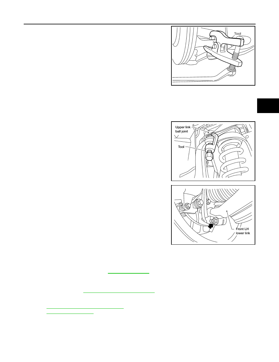
7.
Disconnect steering outer socket from steering knuckle using
Tool. Be careful not to damage ball joint boot.
CAUTION:
To prevent damage to threads and to prevent Tool from
coming off suddenly, temporarily tighten nut.
8.
Remove wheel hub and bearing assembly bolts using power tool.
9.
Remove splash guard and wheel hub and bearing assembly from steering knuckle.
CAUTION:
Do not pull on wheel sensor harness.
10. Remove cotter pin and nut from upper link ball joint.
11. Separate upper link ball joint from steering knuckle using Tool.
12. Remove pinch bolt from steering knuckle using power tool, then
separate lower link ball joint from steering knuckle.
13. Remove steering knuckle from vehicle.
INSPECTION AFTER REMOVAL
Check for deformity, cracks and damage on each part, replace if necessary.
• Perform ball joint inspection. Refer to
.
INSTALLATION
Installation is in the reverse order of removal.
• For 4WD models, refer to
FAX-6, "Removal and Installation"
for drive shaft lock nut tightening torque.
CAUTION:
Always replace drive shaft lock nut and cotter pin.
• Refer to
ST-26, "Disassembly and Assembly"
for outer socket nut tightening torque.
• Refer to
for front suspension tightening torques.
Tool number
: HT72520000 (J-25730-A)
WGIA0130E
Tool number
: ST29020001 (J-24319-01)
WEIA0119E
LEIA0097E