Nissan Frontier D40. Manual - part 608
EM-164
< ON-VEHICLE REPAIR >
[VQ40DE]
FRONT TIMING CHAIN CASE
FRONT TIMING CHAIN CASE
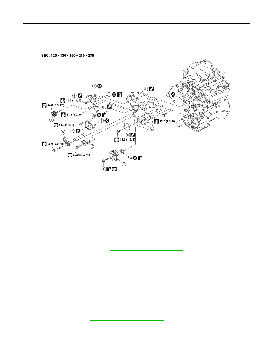
Exploded View
INFOID:0000000005274342
Removal and Installation
INFOID:0000000005274343
REMOVAL
1.
Remove engine room cover. Refer to
EM-138, "Removal and Installation"
2.
Drain engine oil. Refer to
CAUTION:
• Perform this step when engine is cold.
• Do not spill engine oil on drive belts.
3.
Drain engine coolant from radiator. Refer to
CO-39, "Changing Engine Coolant"
.
CAUTION:
• Perform this step when engine is cold.
• Do not spill engine coolant on drive belts.
4.
Remove radiator cooling fan assembly. Refer to
CO-47, "Removal and Installation (Motor driven type)"
5.
Disconnect engine harnesses removing their brackets from front timing chain case.
6.
Remove EVAP canister purge volume control solenoid valve, if necessary.
7.
Remove drive belt. Refer to
EM-127, "Removal and Installation"
8.
Remove power steering oil pump from bracket with piping connected, and temporarily secure it aside.
Refer to
ST-18, "Removal and Installation"
9.
Remove power steering oil pump bracket. Refer to
ST-18, "Removal and Installation"
AWBIA0858GB
1.
O-ring
2.
Collared O-ring
3.
Intake valve timing control cover (RH)
4.
Idler pulley
5.
Drive belt auto tensioner
6.
Intake valve timing control cover (LH)
7.
Collared O-ring
8.
O-ring
9.
Chain tensioner cover
10.
Cooling fan bracket
11.
Crankshaft pulley
12.
Front oil seal
13.
Water pump cover
14.
Front timing chain case
15.
O-ring
A.
Refer to