Nissan Frontier D40. Manual - part 607


  Index      Nissan     Nissan Frontier D40 (2010 year) - Service and Repair Manual


Search            


Content   ..  605  606  607  608   ..


Nissan Frontier D40. Manual - part 607


EM-160

< ON-VEHICLE REPAIR >

[VQ40DE]

FUEL INJECTOR AND FUEL TUBE

4.

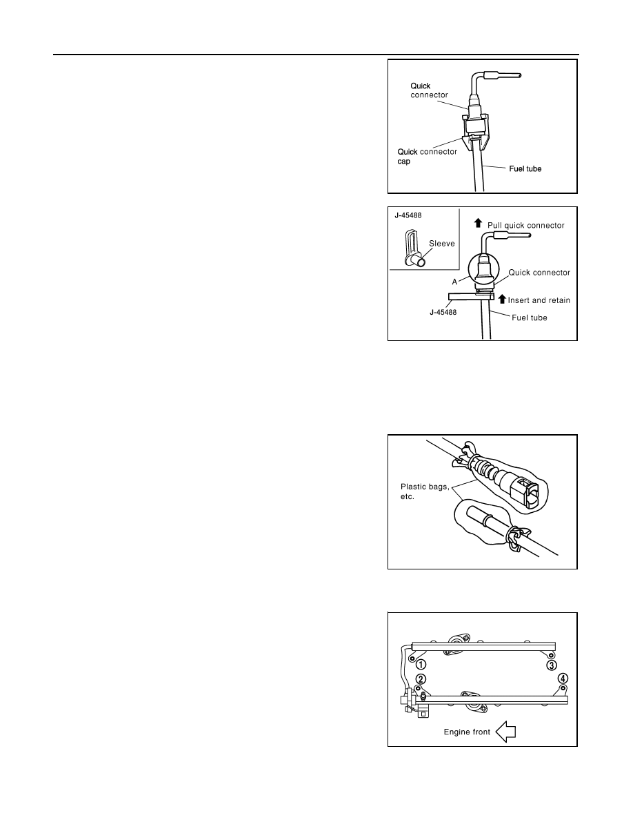
Disconnect the fuel quick connector on the engine side.

a.

Remove quick connector cap.

b.

With the sleeve side of Tool facing quick connector, install Tool
onto fuel tube.

c.

Insert Tool into quick connector until sleeve contacts and goes
no further. Hold the Tool on that position.

CAUTION:

Inserting the Tool hard will not disconnect quick connector.
Hold Tool where it contacts and goes no further.

d.

Pull the quick connector straight out from the fuel tube.

CAUTION:

• Pull quick connector holding it at the (A) position, as shown.
• Do not pull with lateral force applied. O-ring inside quick connector may be damaged.
• Prepare container and cloth beforehand as fuel will leak out.
• Avoid fire and sparks.
• Do not expose parts to battery electrolyte or other acids.
• Do not bend or twist connection between quick connector and fuel feed hose during removal

and installation.

• Be sure to cover openings of disconnected pipes with

plug or plastic bag to avoid fuel leakage and entry of for-
eign materials.

5.

Remove PCV hose between rocker covers (right and left banks).

6.

Disconnect harness connector from fuel injector.

7.

Loosen bolts in reverse order as shown, and remove fuel tube
and fuel injector assembly.

CAUTION:

Do not tilt it, or remaining fuel in pipes may flow out from
pipes.

8.

Remove bolts which connects fuel tube (RH) and fuel tube (LH).

LBIA0090E

Tool number

(J-45488)

WBIA0295E

PBIC1899E

PBIC2902E

FUEL INJECTOR AND FUEL TUBE

EM-161

< ON-VEHICLE REPAIR >

[VQ40DE]

C

D

E

F

G

H

I

J

K

L

M

A

EM

N

P

O

9.

Remove fuel injector from fuel tube as follows:

a.

Carefully open and remove clip.

b.

Remove fuel injector from fuel tube by pulling straight.

CAUTION:

• Be careful with remaining fuel that may leak out from fuel

tube.

• Do not damage injector nozzles during removal.
• Do not bump or drop fuel injectors.
• Do not disassemble fuel injectors.

10. Disconnect fuel tube (RH) from fuel tube (LH).
11. Loosen bolts, to remove fuel damper cap and fuel damper, if necessary.

INSTALLATION

1.

Install fuel damper as follows:

a.

Install new O-ring to fuel tube as shown.
• When handling new O-rings, be careful of the following cau-

tion:

CAUTION:

• Handle O-ring with bare hands. Never wear gloves.
• Lubricate new O-ring with new engine oil.
• Do not clean O-ring with solvent.
• Make sure that O-ring and its mating part are free of for-

eign material.

• When installing O-ring, do not scratch it with tool or fin-

gernails. 

• Do not twist or stretch O-ring. If O-ring was stretched

while it was being attached, allow it to retract before
inserting it into fuel tube.

• Insert new O-ring straight into fuel tube. Do not angle or

twist it.

b.

Install spacer to fuel damper.

c.

Insert fuel damper straight into fuel tube.

CAUTION:

• Insert straight, making sure that the axis is lined up.
• Do not pressure-fit with excessive force.

• Insert fuel damper until (B) is touching (A) of fuel tube.

d.

Tighten bolts evenly in turn.
• After tightening bolts, make sure that there is no gap between fuel damper cap and fuel tube.

2.

Install new O-rings to fuel injector, paying attention to the following.

CAUTION:

• Do not reuse O-rings.
• Upper and lower O-ring are different colors. 

PBIC2999E

Reference value

: 130 N (13.3 kg, 29.2 lb)

PBIC2903E

EM-162

< ON-VEHICLE REPAIR >

[VQ40DE]

FUEL INJECTOR AND FUEL TUBE

• Handle O-ring with bare hands. Never wear gloves.
• Lubricate O-ring with new engine oil.
• Do not clean O-ring with solvent.
• Make sure that O-ring and its mating part are free of foreign material.
• When installing O-ring, be careful not to scratch it with tool or fingernails. 
• Do not twist or stretch O-ring. If O-ring was stretched while it was being attached, allow it to

retract before inserting it into fuel tube.

• Insert O-ring straight into fuel injector. Do not angle or twist it.

3.

Install fuel injector to fuel tube.

a.

Insert new clip into clip mounting groove on fuel injector.
• Insert clip so that protrusion of fuel injector matches cutout of

clip.

CAUTION:

• Do not reuse clip. Replace it with a new one.
• Do not allow the clip to interfere with the O-ring. If inter-

ference occurs, replace O-ring.

b.

Insert the fuel injector into the fuel tube with the clip attached.
• Insert it while matching it to the axial center.
• Insert fuel injector so that protrusion of fuel tube matches cut-

out of clip.

• Make sure that fuel tube flange is securely fixed in flange fixing

groove on clip.

c.

Make sure that installation is complete by checking that the fuel
injector does not rotate or come off.
• Make sure that protrusions of the fuel injectors are aligned

with cutouts of clips after installation.

4.

Connect the fuel tube (RH) to the fuel tube (LH), and tighten bolts temporarily.
• Tighten bolts to the specified torque after installing fuel tube and fuel injector assembly.

CAUTION:

• Handle O-ring with bare hands. Do not wear gloves.
• Lubricate O-ring with new engine oil.
• Do not clean O-ring with solvent.
• Make sure that O-ring and its mating part are free of foreign material.
• When installing O-ring, be careful not to scratch it with tool or fingernails. 
• Do not twist or stretch O-ring. If O-ring was stretched while it was being attached, allow it to

retract before inserting it into fuel tube.

• Insert new O-ring straight into fuel tube. Do not angle or twist it.

5.

Install fuel tube and fuel injector assembly to intake manifold.

CAUTION:

Do not let the tip of the injector nozzle come in contact with other parts.

Fuel tube side

: Blue

Nozzle side

: Brown

PBIC3000E

FUEL INJECTOR AND FUEL TUBE

EM-163

< ON-VEHICLE REPAIR >

[VQ40DE]

C

D

E

F

G

H

I

J

K

L

M

A

EM

N

P

O

• Tighten bolts in two steps in numerical order as shown.

6.

Tighten bolts which connect fuel tube (RH) and fuel tube (LH) to the specified torque.

7.

Connect fuel injector harness connector.

8.

Install intake manifold collector. Refer to 

EM-140, "Removal and Installation"

.

9.

Installation of the remaining components is in the reverse order of removal.

INSPECTION AFTER INSTALLATION

Check on Fuel Leakage

1.

Apply fuel pressure to the fuel lines by turning ignition switch ON (with engine stopped). Then check for
fuel leaks at the connections.

2.

Start the engine and rev it up and check for fuel leaks at the connections.

WARNING:

Do not touch engine immediately after stopping, as engine becomes extremely hot.
NOTE:
Use mirrors for checking at points out of clear sight.

Fuel injector tube assembly bolts

 1st step

: 10.1 N·m (1.0 kg-m, 7 ft-lb)

 2nd step

: 22.0 N·m (2.2 kg-m, 16 ft-lb)

PBIC2902E


Content   ..  605  606  607  608   ..