Nissan Frontier D40. Manual - part 601
EM-136
< ON-VEHICLE MAINTENANCE >
[VQ40DE]
COMPRESSION PRESSURE
COMPRESSION PRESSURE
Compression Pressure
INFOID:0000000005274324
CHECKING COMPRESSION PRESSURE
1.
Warm up engine thoroughly.
2.
Release fuel pressure. Refer to
.
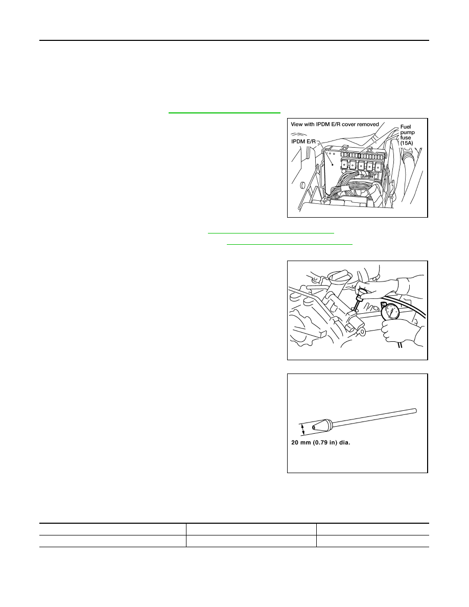
3.
Disconnect fuel pump fuse to avoid fuel injection during mea-
surement.
4.
Remove intake manifold collector. Refer to
EM-140, "Removal and Installation"
5.
Remove spark plug from each cylinder. Refer to
EM-130, "Removal and Installation"
.
6.
Connect engine tachometer (not required in use of CONSULT-III).
7.
Install compression tester with adapter onto spark plug hole.
• Use compression gauge whose pick up end inserted to spark
plug hole is smaller than 20 mm (0.79 in) in diameter. Other-
wise, it may be caught by cylinder head during removal.
8.
Turn ignition switch to “START” for cranking. When the gauge pointer stabilizes, read the compression
pressure and engine rpm. Perform these steps to check each cylinder.
Compression pressure:
Unit: kPa (kg/cm
2
, psi) /rpm
CAUTION:
Always use a fully charged battery to obtain specified engine speed.
• If the engine speed is out of the specified range, check the battery liquid for proper gravity. Check the
engine speed again with normal battery gravity.
BBIA0534E
PBIC0900E
SBIA0533E
Standard
Minimum
Differential limit between cylinders
1,275 (13.0, 185) / 300
981 (10.0, 142) / 300
98 (1.0, 14) / 300