Nissan Frontier D40. Manual - part 588
EM-84
< DISASSEMBLY AND ASSEMBLY >
[QR25DE]
ENGINE UNIT
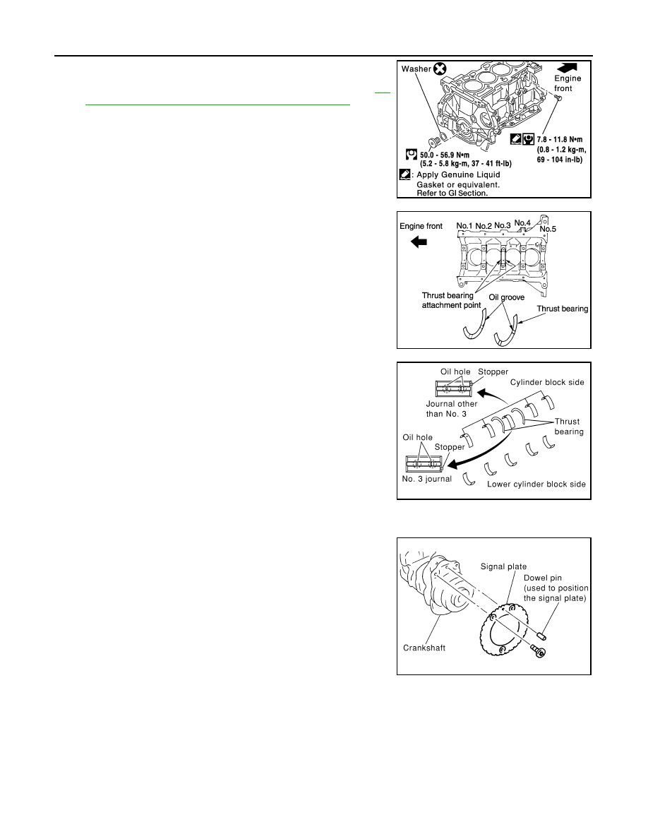
2.
Apply Silicone RTV Sealant to the drain plugs. Install the drain
plugs on the cylinder block.
• Use Genuine Silicone RTV Sealant, or equivalent. Refer to
22, "Recommended Chemical Products and Sealants"
.
• Replace the copper washers with new ones.
3.
Install main bearings and thrust bearings as follows:
a.
Remove dust, dirt, and engine oil from the bearing mating sur-
faces of the cylinder block and lower cylinder block.
b.
Install the thrust bearings to both sides of the No. 3 main bearing
journal on the cylinder block.
• Install the thrust bearings with the oil groove facing the crank-
shaft arm (outside).
c.
Install the main bearings paying attention to their position and
direction.
• The main bearing with an oil hole and groove goes on the cyl-
inder block. The one without them goes on the lower cylinder
block.
• Only the main bearing (on the cylinder block) for No. 3 journal
has different specifications.
• Before installing the bearings, apply engine oil to the bearing
friction surface (inside). Do not apply oil to the back surface,
but thoroughly clean it.
• When installing, align the bearing stopper to the notch.
• Make sure that the oil holes on the cylinder block and those on
the corresponding bearing are aligned.
4.
Install the signal plate to the crankshaft.
a.
Position the crankshaft and signal plate using a positioning
dowel pin, and tighten the signal plate bolts to specification.
b.
Remove the dowel pin.
CAUTION:
Be sure to remove dowel pin before installing the crank-
shaft.
NOTE:
Dowel pins for the crankshaft and signal plate are supplied as a set for each.
5.
Install crankshaft to the cylinder block.
• While turning the crankshaft by hand, check that it turns smoothly.
CAUTION:
Do not install rear oil seal at this time.
WBIA0159E
PBIC0264E
SBIA0277E
Signal plate bolts
Type 1
: 18.5 N·m (1.9 kg-m, 14 ft-lb)
Type 2
: 22.0 N·m (2.2 kg-m, 16 ft-lb)
SBIA0278E