Nissan Frontier D40. Manual - part 585


  Index      Nissan     Nissan Frontier D40 (2010 year) - Service and Repair Manual


Search            


Content   ..  583  584  585  586   ..


Nissan Frontier D40. Manual - part 585


EM-72

< ON-VEHICLE REPAIR >

[QR25DE]

CYLINDER HEAD

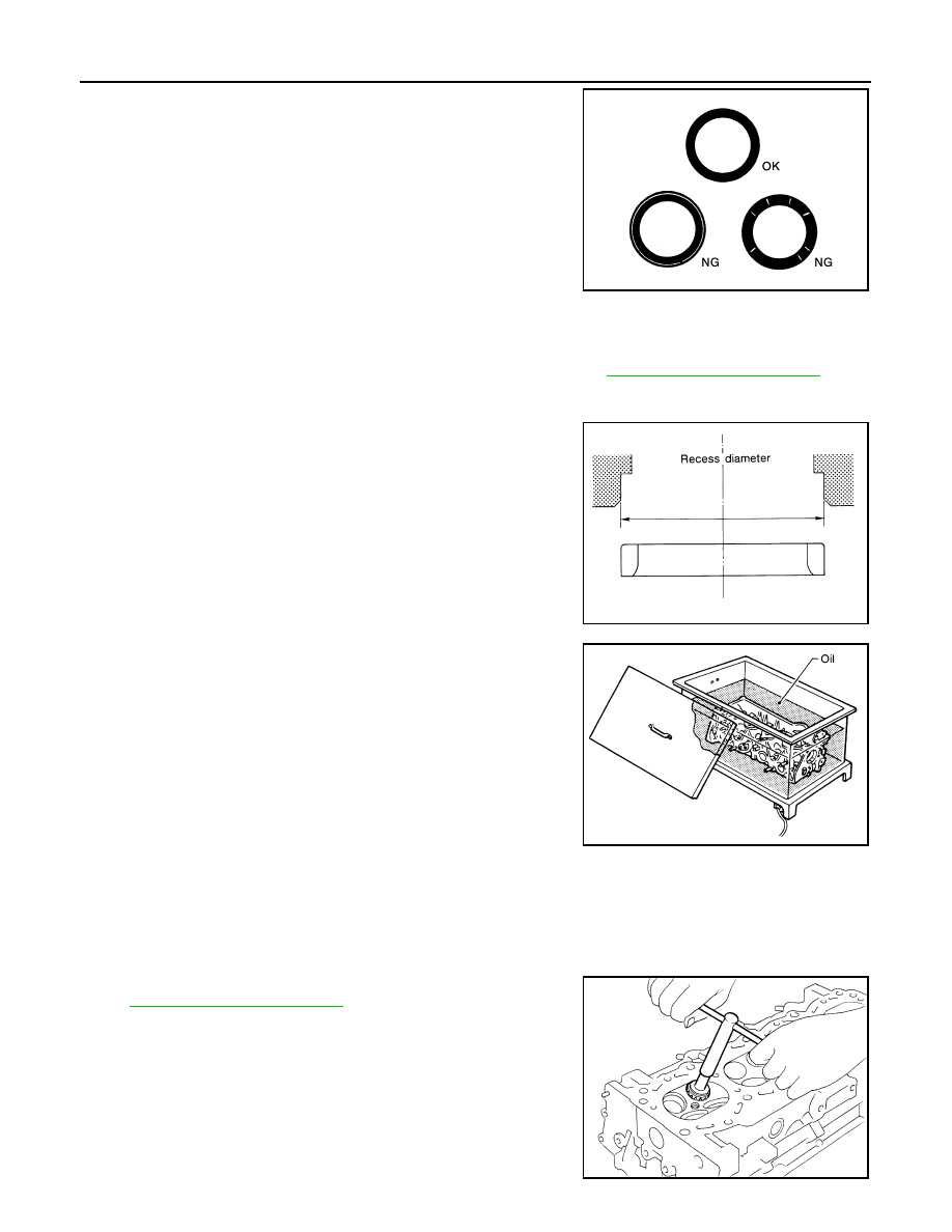
• After confirming that the dimensions of valve guides and valves are

within specifications, perform this procedure. 

• Apply prussian blue (or white lead) onto contacting surface of valve

seat to check the condition of the valve contact on the surface.

• Check if the contact area band is continuous all around the circum-

ference.

• If not, grind to adjust valve fitting and check again. If the contacting

surface still has NG conditions even after the re-check, replace
valve seat.

VALVE SEAT REPLACEMENT

When valve seat is removed, replace with oversized [0.5 mm (0.020 in)] valve seat.

1.

Bore out old seat until it collapses. Boring should not continue beyond the bottom face of the seat recess
in cylinder head. Set the machine depth stop to ensure this. Refer to 

EM-106, "Standard and Limit"

.

CAUTION:

Prevent scratching cylinder head by excessive boring.

2.

Ream cylinder head recess diameter for service valve seat.

• Be sure to ream in circles concentric to the valve guide center.

This will enable valve seat to fit correctly.

3.

Heat cylinder head to 110

°

 to 130

°

C (230

°

 to 266

°

F) by soaking

in heated oil.

4.

Provide valve seats cooled well with dry ice. Force fit valve seats into cylinder head.

WARNING:

• Cylinder head contains heat. When working, wear protective equipment to avoid getting burned.

CAUTION:

• Avoid directly touching cold valve seats.

5.

Finish seat to the specified dimensions using suitable tool. Refer
to 

EM-106, "Standard and Limit"

.

CAUTION:

When using valve seat cutter, firmly grip cutter handle with
both hands. Then, press on the contacting surface all
around the circumference to cut in a single drive. Improper
pressure on the cutter or cutting many different times may
result in staged valve seat. 

SBIA0322E

Oversize [0.5 mm (0.020 in)]

Intake

: 37.000 - 37.016 mm (1.4567 - 1.4573 in)

Exhaust

: 32.000 - 32.016 mm (1.2598 - 1.2605 in)

SEM795A

SEM008A

SEM934C

CYLINDER HEAD

EM-73

< ON-VEHICLE REPAIR >

[QR25DE]

C

D

E

F

G

H

I

J

K

L

M

A

EM

N

P

O

6.

Using compound, grind to adjust valve fitting. 

7.

Check again for normal contact.

VALVE SPRING SQUARENESS

• Set a try square along the side of valve spring and rotate spring.

Measure the maximum clearance between the top face of spring
and try square.

CAUTION:

Do not remove valve spring seat from valve spring.

• If it exceeds the limit, replace valve spring.

VALVE SPRING DIMENSIONS AND VALVE SPRING PRESSURE LOAD

• Check valve spring pressure with valve spring seat installed at the

specified spring height. Refer to 

EM-106, "Standard and Limit"

.

CAUTION:

Do not remove valve spring seat from valve spring.

• If the installation load or load with valve open is out of the stan-

dard, replace valve spring.

Limit

Intake

: 1.8 mm (0.071 in)

Exhaust

: 1.9 mm (0.075 in)

PBIC0080E

SEM113

EM-74

< REMOVAL AND INSTALLATION >

[QR25DE]

ENGINE ASSEMBLY

REMOVAL AND INSTALLATION

ENGINE ASSEMBLY

Exploded View

INFOID:0000000005274295

Removal and Installation

INFOID:0000000005274296

WARNING:

• Situate vehicle on a flat and solid surface.
• Place chocks at front and back of rear wheels.
• For engines not equipped with engine slingers, attach proper slingers and bolts described in PARTS

CATALOG.

CAUTION:

• Always be careful to work safely, avoid forceful or uninstructed operations.
• Do not start working until exhaust system and engine coolant are cooled sufficiently.
• If items or work required are not covered by the engine section, follow the procedures in the applica-

ble procedures.

• Always use the support point specified for lifting.
• Use either 2-pole lift type or separate type lift. If board-on type is used for unavoidable reasons, sup-

port at the rear axle jacking point with transmission jack or similar tool before starting work, in prep-
aration for the backward shift of center of gravity.

• For supporting points for lifting and jacking point at rear axle, refer to 

GI-38, "Garage Jack and

Safety Stand"

.

1. RH engine mounting bracket (upper)

2. RH engine mounting insulator

3. RH engine mounting bracket (lower)

4. LH engine mounting bracket (upper)

5. LH engine mounting insulator

6. LH engine mounting bracket (lower)

7. Rear engine mounting insulator

AWBIA0869GB

ENGINE ASSEMBLY

EM-75

< REMOVAL AND INSTALLATION >

[QR25DE]

C

D

E

F

G

H

I

J

K

L

M

A

EM

N

P

O

REMOVAL

1.

Remove engine under cover. Refer to 

EXT-13, "Removal and Installation"

.

2.

Drain engine coolant. Refer to 

CO-12, "Changing Engine Coolant"

.

3.

Partially drain A/T fluid (A/T models). Refer to 

TM-263, "Changing the A/T Fluid (ATF)"

.

4.

Release fuel pressure. Refer to 

EC-454, "Fuel Pressure Check"

.

5.

Disconnect battery negative terminal. Refer to 

PG-84, "Removal and Installation"

.

6.

Remove the engine hood. Refer to 

DLK-127, "Removal and Installation of Hood Assembly"

.

7.

Remove the air duct and resonator assembly and air cleaner case. Refer to 

EM-25, "Removal and Instal-

lation"

.

8.

Disconnect vacuum hose between vehicle and engine and set it aside.

9.

Remove the radiator assembly and hoses. Refer to 

CO-16, "Removal and Installation"

.

10. Remove the drive belt. Refer to 

EM-14, "Removal and Installation"

11. Remove the engine cooling fan. Refer to 

CO-19, "Removal and Installation (Crankshaft driven type)"

.

12. Disconnect the engine room harness from the engine side and set it aside for easier work.

13. Disconnect the engine harness grounds.
14. Disconnect the reservoir tank for power steering from engine and move it aside for easier work.

15. Disconnect power steering oil pump from engine and position out of the way for easier work. Refer to 

ST-

18, "Removal and Installation"

16. Remove the A/C compressor bolts and set aside. Refer to 

HA-28, "Removal and Installation for Compres-

sor"

.

17. Disconnect brake booster vacuum line.
18. Disconnect EVAP line.

19. Disconnect the fuel hose at the engine side connection. Refer to 

EM-38, "Removal and Installation"

.

20. Disconnect the heater hoses at cowl, and install plugs to avoid leakage of engine coolant.
21. Remove the A/T oil level indicator and indicator tube (A/T models).

22. Remove front exhaust pipe. Refer to 

EM-30, "Removal and Installation"

.

23. Install front and rear engine slingers.

24. Remove transmission. Refer to 

TM-19, "Removal and Installa-

tion from Vehicle"

 (M/T models), 

TM-299, "Removal and Installa-

tion for QR25DE"

 (A/T models).

25. Lift with hoist and secure the engine in position.

26. Remove engine assembly from vehicle, avoiding interference

with vehicle body.

CAUTION:

• Before and during this lifting, always check if any harnesses are left connected.

27. Remove the parts that may restrict installation of engine to engine stand.

NOTE:
The procedure is described assuming that you use a engine holding the surface, to which transmission is
installed.

a.

Remove drive plate (A/T models) or flywheel (M/T models).
• Holding crankshaft pulley bolts, lock crankshaft to remove flywheel or drive plate bolts.
• Loosen bolts diagonally.

CAUTION:

Engine slinger torque

Front engine slinger

: 48.1 N·m (4.9 kg-m, 35 ft-lb)

Rear engine slinger

: 22.0 N·m (2.2 kg-m, 16 ft-lb)

LBIA0449E


Content   ..  583  584  585  586   ..