Nissan Frontier D40. Manual - part 582


  Index      Nissan     Nissan Frontier D40 (2010 year) - Service and Repair Manual


Search            


Content   ..  580  581  582  583   ..


Nissan Frontier D40. Manual - part 582


EM-60

< ON-VEHICLE REPAIR >

[QR25DE]

CAMSHAFT

16. Installation is in the reverse order of removal after this step.

NOTE:
If hydraulic pressure inside timing chain tensioner drops after removal and installation, slack in the guide
may generate a pounding noise during and just after the engine start. However, this is normal. Noise will
stop after hydraulic pressure rises.

INSPECTION AFTER INSTALLATION

Inspection of Camshaft Sprocket (INT) Oil Groove

CAUTION:

• Perform this inspection only when DTC P0011 is detected in self-diagnostic results of CONSULT-III

and it is directed according to inspection procedure of EC section. Refer to 

EC-96, "Component

Inspection"

.

• Check when the engine is cold so as to prevent burns from any splashing engine oil.

1.

Check the engine oil level. Refer to 

LU-9, "Inspection"

.

2.

Perform the following procedure so as to prevent the engine from being unintentionally started while
checking.

a.

Release fuel pressure. Refer to 

EC-454, "Fuel Pressure Check"

.

b.

Disconnect ignition coil and injector harness connectors.

c.

Remove drive belt. Refer to 

EM-14, "Removal and Installation"

.

3.

Remove intake valve timing control solenoid valve. Refer to 

EM-43, "Exploded View"

.

4.

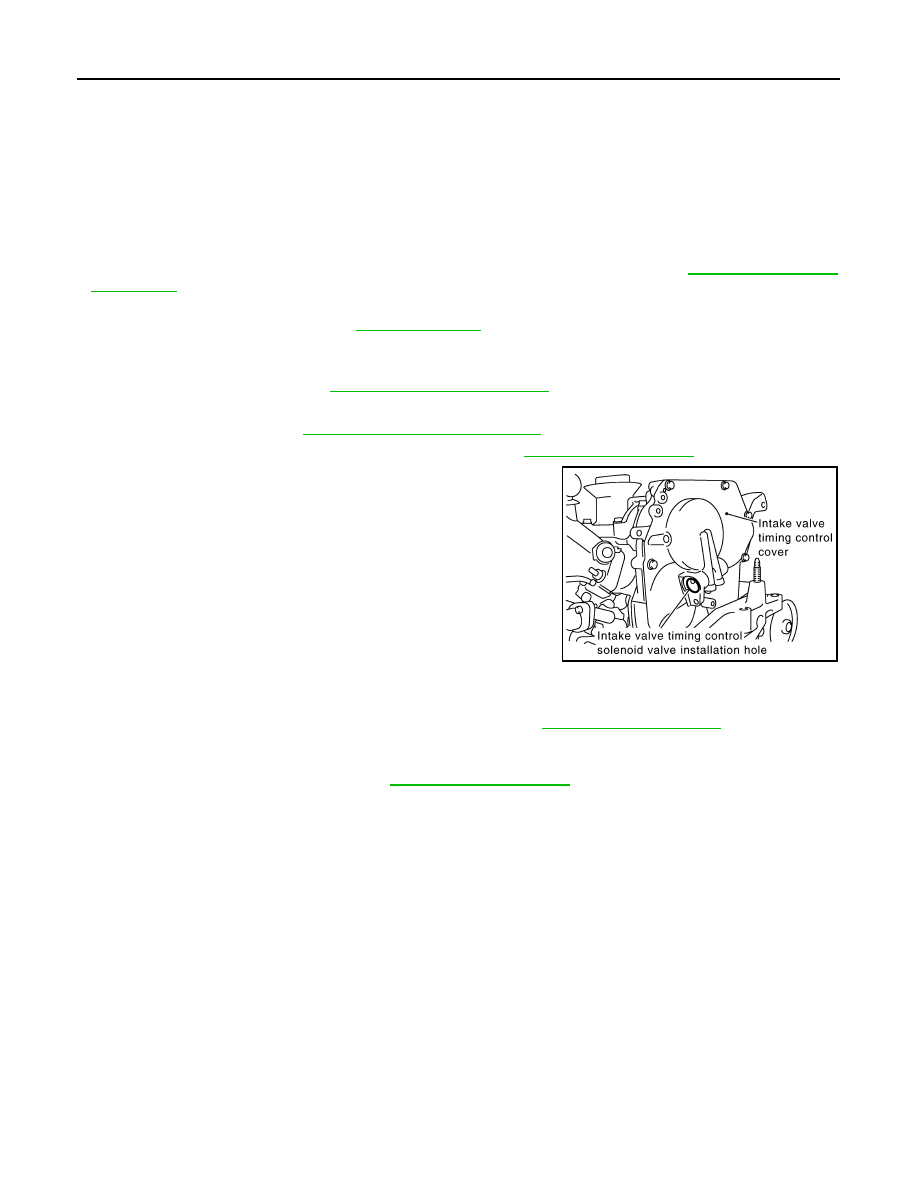
Crank the engine, and then make sure that engine oil comes out
from intake valve timing control cover oil hole. Stop cranking
after checking.

WARNING:

Be careful not to touch rotating parts (drive belt, idler pul-
ley, and crankshaft pulley, etc.).

CAUTION:

Engine oil may squirt from intake valve timing control sole-
noid valve installation hole during cranking. Use a shop
cloth to protect the engine components and the vehicle. Do
not allow engine oil to get on rubber components such as
drive belt or engine mount insulators. Immediately wipe off
any splashed engine oil.

• Clean oil groove between oil strainer and intake valve timing control solenoid valve if engine oil does not

come out from intake valve timing control cover oil hole. Refer to 

LU-7, "Lubrication Circuit"

.

5.

Remove components between intake valve timing control solenoid valve and camshaft sprocket (INT),
and then check each oil groove for clogging.
• Clean oil groove if necessary. Refer to 

LU-7, "Lubrication Circuit"

.

6.

Installation is in the reverse order of removal.

PBIC2723E

OIL SEAL

EM-61

< ON-VEHICLE REPAIR >

[QR25DE]

C

D

E

F

G

H

I

J

K

L

M

A

EM

N

P

O

OIL SEAL

Removal and Installation of Valve Oil Seal

INFOID:0000000005274287

REMOVAL

1.

Remove fan shroud (lower). Refer to 

CO-16, "Exploded View"

.

2.

Turn crankshaft until the cylinder requiring new oil seals is at TDC. This will prevent valve from dropping
into cylinder.

3.

Remove camshaft relating to valve oil seal to be removed. Refer to 

EM-52

.

4.

Remove valve lifters. Refer to 

EM-52

.

5.

Remove valve collet, valve spring retainer and valve spring
using Tool. 

CAUTION:

• When working, be careful not to damage valve lifter holes.
• Do not remove valve spring seat from valve spring.

• Compress valve spring using Tool. Remove valve collet with

magnetic hand.

6.

Remove valve oil seal using Tool.

INSTALLATION

1.

Apply new engine oil to valve oil seal joint surface and seal lip.

2.

Press in valve oil seal to the height (H) as shown using Tool.

3.

Installation of the remaining components is in the reverse order of removal.

Removal and Installation of Front Oil Seal

INFOID:0000000005274288

REMOVAL

1.

Remove engine under cover. Refer to 

EXT-13, "Removal and Installation"

.

2.

Remove fan shroud (lower). Refer to 

CO-16, "Exploded View"

3.

Remove cooing fan. Refer to 

CO-19, "Removal and Installation (Crankshaft driven type)"

.

4.

Remove drive belt. Refer to 

EM-14, "Removal and Installation"

.

Tool numbers

: KV10116200 (J-26336-A)

: KV10115900 (J-26336-20)

WBIA0477E

Tool numbers

: KV10107902 (J-38959)

WBIA0478E

Tool numbers

: KV10115600 (J-38958)

WBIA0653E

EM-62

< ON-VEHICLE REPAIR >

[QR25DE]

OIL SEAL

5.

Remove crankshaft pulley. Refer to 

EM-44

.

6.

Remove front oil seal using a suitable tool.

CAUTION:

Be careful not to damage front cover and crankshaft.

INSTALLATION

1.

Apply new engine oil to both oil seal lip and dust seal lip of new front oil seal.

2.

Install front oil seal.
• Install front oil seal so that each seal lip is oriented as shown.

• Press-fit front oil seal until it is flush with front end surface of

front cover using suitable tool.

CAUTION:

• Be careful not to damage front cover and crankshaft.
• Press-fit straight and avoid causing burrs or tilting oil

seal.

3.

Installation is in the reverse order of removal after this step.

Removal and Installation of Rear Oil Seal

INFOID:0000000005274289

REMOVAL

1.

Remove transmission assembly. Refer to 

TM-19, "Removal and Installation from Vehicle"

 (M/T models),

TM-299, "Removal and Installation for QR25DE"

 (A/T models).

2.

Remove clutch cover and clutch disk (M/T models). Refer to 

CL-20, "5M/T : Removal and Installation"

3.

Remove drive plate (A/T models) or flywheel (M/T models) with power tool. Refer to 

EM-78, "Exploded

View"

.

4.

Remove rear oil seal with a suitable tool.

CAUTION:

Be careful not to damage crankshaft and cylinder block.

INSTALLATION

1.

Apply new engine oil to new rear oil seal joint surface and seal lip.

SEM829E

SEM715A

PBIC3033E

OIL SEAL

EM-63

< ON-VEHICLE REPAIR >

[QR25DE]

C

D

E

F

G

H

I

J

K

L

M

A

EM

N

P

O

2.

Install rear oil seal so that each seal lip is oriented as shown.

• Install new rear oil seal using suitable tool. [outside diameter

102 mm (4.02 in), inside diameter 86 mm (3.39 in)].

CAUTION:

• Be careful not to damage crankshaft and cylinder block.
• Press-fit oil seal straight to avoid causing burrs or tilt-

ing.

• Do not touch grease applied onto oil seal lip.

• Press in rear oil seal to the position as shown.

3.

Installation of the remaining components is in the reverse order of removal.

CAUTION:

• When replacing an engine or transmission you must make sure the dowels are installed correctly

during reassembly.

• Improper alignment caused by missing dowels may cause vibration, oil leaks or breakage of driv-

etrain components.

SEM715A

SBIA0280E

WBIA0654E


Content   ..  580  581  582  583   ..