Nissan Frontier D40. Manual - part 580
EM-52
< ON-VEHICLE REPAIR >
[QR25DE]
CAMSHAFT
CAMSHAFT
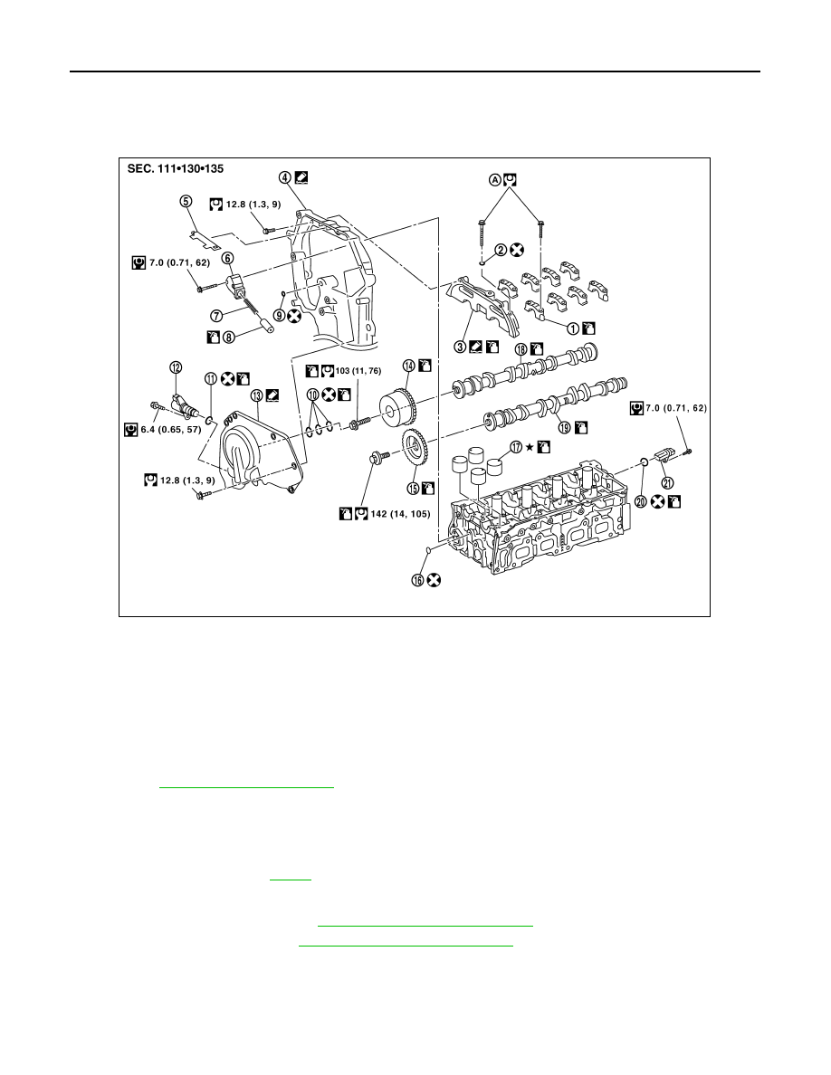
Exploded View
INFOID:0000000005274285
Removal and Installation
INFOID:0000000005274286
NOTE:
This section describes removal/installation procedure of camshaft without removing front cover. If front cover
is removed or installed, refer to
.
REMOVAL
1.
Remove the rocker cover. Refer to
EM-36, "Removal and Installation"
.
2.
Remove the drive belt. Refer to
EM-14, "Removal and Installation"
.
3.
Disconnect and remove the camshaft position sensor (PHASE).
4.
Disconnect the IVT control solenoid electrical connector.
5.
Disconnect the ground electrical connections from the front cover.
1.
Camshaft bracket (No. 2 to 5)
2.
Seal washer
3.
Camshaft bracket (No. 1)
4.
Front cover
5.
Chain guide
6.
Chain tensioner
7.
Spring
8.
Chain tensioner plunger
9.
O-ring
10. Oil ring
11.
O-ring
12.
Intake valve timing control solenoid
valve
13. Intake valve timing control cover
14. Camshaft sprocket (INT)
15. Camshaft sprocket (EXH)
16. O-ring
17. Valve lifter
18. Camshaft (INT)
19. Camshaft (EXH)
20. O-ring
21. Camshaft position sensor (PHASE)
A.
EM-52, "Removal and Installation"
WBIA0833E