Nissan Frontier D40. Manual - part 577
EM-40
< ON-VEHICLE REPAIR >
[QR25DE]
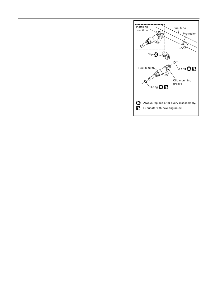
FUEL INJECTOR AND FUEL TUBE
6.
Remove fuel injector from fuel tube as follows:
a.
Carefully open and remove clip.
b.
Remove fuel injector from fuel tube by pulling straight.
CAUTION:
• Be careful with remaining fuel that may leak out from fuel
tube.
• Do not damage fuel injector nozzles during removal.
• Do not bump or drop fuel injectors.
• Do not disassemble fuel injectors.
INSTALLATION
1.
Install new O-rings to fuel injector, paying attention to the following.
CAUTION:
• Upper and lower O-rings are different colors.
• Handle O-ring with bare hands. Do not wear gloves.
• Lubricate O-ring with new engine oil.
• Do not clean O-ring with solvent.
• Make sure that O-ring and its mating part are free of foreign material.
• When installing O-ring, be careful not to scratch it with tool or fingernails.
• Do not twist or stretch O-ring. If O-ring was stretched while it was being attached, allow it to
retract before inserting it into fuel tube.
• Insert new O-ring straight into fuel tube. Do not angle or twist it.
PBIC2999E
Fuel tube side
: Black
Nozzle side
: Green