Nissan Frontier D40. Manual - part 536


  Index      Nissan     Nissan Frontier D40 (2010 year) - Service and Repair Manual


Search            


Content   ..  534  535  536  537   ..


Nissan Frontier D40. Manual - part 536


P2135 TP SENSOR

EC-835

< COMPONENT DIAGNOSIS >

[VQ40DE]

C

D

E

F

G

H

I

J

K

L

M

A

EC

N

P

O

>> INSPECTION END

Component Inspection

INFOID:0000000005273856

THROTTLE POSITION SENSOR

1.

Reconnect all harness connectors disconnected.

2.

Perform 

EC-473, "Throttle Valve Closed Position Learning"

.

3.

Turn ignition switch ON.

4.

Set selector lever to D (A/T), 1st (M/T). 

5.

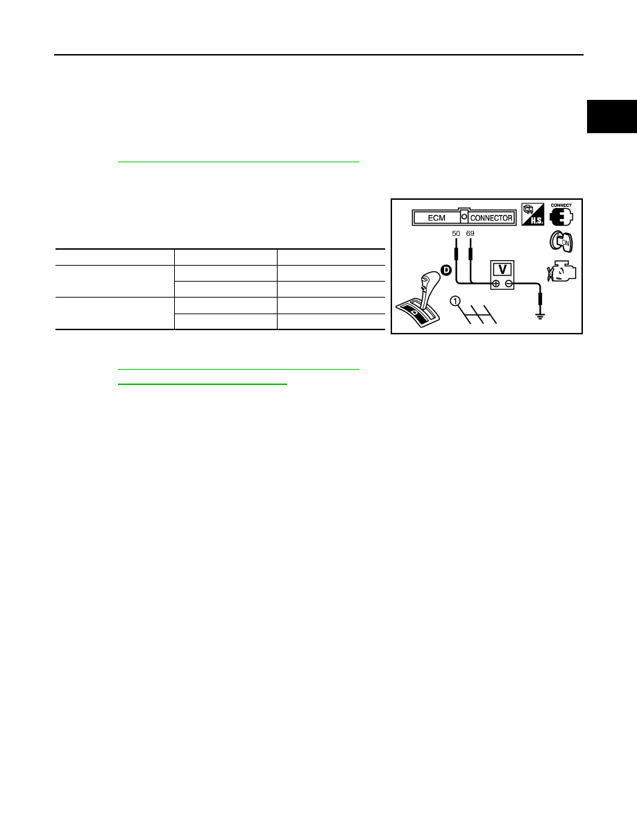
Check voltage between ECM terminals 50 (TP sensor 1 signal),
69 (TP sensor 2 signal) and ground under the following condi-
tions.

6.

If NG, replace electric throttle control actuator and go to the next
step.

7.

Perform 

EC-473, "Throttle Valve Closed Position Learning"

.

8.

Perform 

EC-473, "Idle Air Volume Learning"

.

Terminal

Accelerator pedal

Voltage

50
(Throttle position sensor 1)

Fully released

More than 0.36V

Fully depressed

Less than 4.75V

69
 (Throttle position sensor 2)

Fully released

Less than 4.75V

Fully depressed

More than 0.36V

PBIB1170E

EC-836

< COMPONENT DIAGNOSIS >

[VQ40DE]

P2138 APP SENSOR

P2138 APP SENSOR

Component Description

INFOID:0000000005273857

The accelerator pedal position sensor is installed on the upper end
of the accelerator pedal assembly. The sensor detects the accelera-
tor position and sends a signal to the ECM.
Accelerator pedal position sensor has two sensors. These sensors
are a kind of potentiometers which transform the accelerator pedal
position into output voltage, and emit the voltage signal to the ECM.
In addition, these sensors detect the opening and closing speed of
the accelerator pedal and feed the voltage signals to the ECM. The
ECM judges the current opening angle of the accelerator pedal from
these signals and controls the throttle control motor based on these
signals.
Idle position of the accelerator pedal is determined by the ECM
receiving the signal from the accelerator pedal position sensor. The ECM uses this signal for the engine oper-
ation such as fuel cut.

On Board Diagnosis Logic

INFOID:0000000005273858

This self-diagnosis has the one trip detection logic.
NOTE:
If DTC P2138 is displayed with DTC P0643, first perform the trouble diagnosis for DTC P0643. Refer to

EC-758

.

FAIL-SAFE MODE

When the malfunction is detected, ECM enters fail-safe mode and the MIL illuminates.

DTC Confirmation Procedure

INFOID:0000000005273859

NOTE:
If DTC Confirmation Procedure has been previously conducted, always perform the following before conduct-
ing the next step.
1.

Turn ignition switch OFF and wait at least 10 seconds.

2.

Turn ignition switch ON.

3.

Turn ignition switch OFF and wait at least 10 seconds.

TESTING CONDITION:
Before performing the following procedure, confirm that battery voltage is more than 10V at idle.
1.

Start engine and let it idle for 1 second.

2.

Check DTC.

3.

If DTC is detected, go to 

EC-837, "Diagnosis Procedure"

.

PBIB1741E

DTC No.

Trouble diagnosis name

DTC detecting condition

Possible cause

P2138
2138

Accelerator pedal posi-
tion sensor circuit range/
performance 

Rationally incorrect voltage is sent to ECM 
compared with the signals from APP sensor 1 
and APP sensor 2.

• Harness or connector

(The APP sensor 1 and 2 circuit is open 
or shorted.)
(The TP sensor circuit is shorted.)

• Accelerator pedal position sensor

(APP sensor 1 and 2)

• Electric throttle control actuator

(TP sensor 1 and 2)

Engine operating condition in fail-safe mode

The ECM controls the electric throttle control actuator in regulating the throttle opening in order for the idle position to be within +10 
degrees.
The ECM regulates the opening speed of the throttle valve to be slower than the normal condition.
So, the acceleration will be poor. 

P2138 APP SENSOR

EC-837

< COMPONENT DIAGNOSIS >

[VQ40DE]

C

D

E

F

G

H

I

J

K

L

M

A

EC

N

P

O

Diagnosis Procedure

INFOID:0000000005273860

1.

CHECK GROUND CONNECTIONS

1.

Turn ignition switch OFF.

2.

Loosen and retighten three ground screws on the body. Refer to 

EC-549, "Ground Inspection"

.

OK or NG

OK

>> GO TO 2.

NG

>> Repair or replace ground connections.

2.

CHECK APP SENSOR 1 POWER SUPPLY CIRCUIT

1.

Disconnect accelerator pedal position (APP) sensor harness connector.

2.

Turn ignition switch ON.

3.

Check voltage between APP sensor terminals 2 and ground with
CONSULT-III or tester.

OK or NG

OK

>> GO TO 3.

NG

>> Repair open circuit or short to ground or short to power

in harness or connectors.

3.

CHECK APP SENSOR 2 POWER SUPPLY CIRCUIT-I

Check voltage between APP sensor terminal 1 and ground with
CONSULT-III or tester. 

1.

OK or NG

OK

>> GO TO 8.

NG

>> GO TO 4.

4.

CHECK APP SENSOR 2 POWER SUPPLY CIRCUIT-II

1.

Turn ignition switch OFF.

BBIA0539E

Voltage: Approximately 5V

BBIA0556E

PBIB2608E

Voltage: Approximately 5V

PBIB2611E

EC-838

< COMPONENT DIAGNOSIS >

[VQ40DE]

P2138 APP SENSOR

2.

Disconnect ECM harness connector.

3.

Check harness continuity between APP sensor terminal 1 and ECM terminal 91.
Refer to wiring diagram.

OK or NG

OK

>> GO TO 5.

NG

>> Repair open circuit.

5.

CHECK APP SENSOR 2 POWER SUPPLY CIRCUIT-III

Check harness for short to power and short to ground, between the following terminals.

OK or NG

OK

>> GO TO 6.

NG

>> Repair open circuit or short to ground or short to power in harness or connectors.

6.

CHECK THROTTLE POSITION SENSOR

Refer to 

EC-656, "Component Inspection"

.

OK or NG

OK

>> GO TO 12.

NG

>> GO TO 7.

7.

REPLACE ELECTRIC THROTTLE CONTROL ACTUATOR

1.

Replace electric throttle control actuator.

2.

Perform 

EC-473, "Throttle Valve Closed Position Learning"

.

3.

Perform 

EC-473, "Idle Air Volume Learning"

.

>> INSPECTION END

8.

CHECK APP SENSOR GROUND CIRCUIT FOR OPEN AND SHORT

1.

Turn ignition switch OFF.

2.

Disconnect ECM harness connector.

3.

Check harness continuity between APP sensor terminals 4 and ECM terminal 82, APP sensor terminal 5
and ECM terminal 83.
Refer to Wiring Diagram.

4.

Also check harness for short to ground and short to power.

OK or NG

OK

>> GO TO 9.

NG

>> Repair open circuit or short to ground or short to power in harness or connectors.

9.

CHECK APP SENSOR INPUT SIGNAL CIRCUIT FOR OPEN AND SHORT

1.

Check harness continuity between ECM terminal 106 and APP sensor terminal 3, ECM terminal 98 and
APP sensor terminal 6.
Refer to Wiring Diagram.

2.

Also check harness for short to ground and short to power.

OK or NG

OK

>> GO TO 10.

NG

>> Repair open circuit or short to ground or short to power in harness or connectors.

Continuity should exist.

ECM terminal

Sensor terminal

91

APP sensor terminal 1

47

Electric throttle control actuator terminal 2

Continuity should exist.

Continuity should exist.


Content   ..  534  535  536  537   ..