Nissan Frontier D40. Manual - part 485
P0139, P0159 HO2S2
EC-631
< COMPONENT DIAGNOSIS >
[VQ40DE]
C
D
E
F
G
H
I
J
K
L
M
A
EC
N
P
O
Perform component function check. Refer to
EC-631, "Overall Function Check"
.
NOTE:
Use component function check to check the overall function of the heated oxygen sensor 2 circuit. During this
check, a 1st trip DTC might not be confirmed.
Is the inspection result normal?
YES
>> INSPECTION END
NO
>> Proceed to
Overall Function Check
INFOID:0000000005273602
Use this procedure to check the overall function of the heated oxygen sensor 2 circuit. During this check, a 1st
trip DTC might not be confirmed.
WITH GST
1.
Start engine and warm it up to the normal operating temperature.
2.
Turn ignition switch OFF and wait at least 10 seconds.
3.
Turn ignition switch ON.
4.
Turn ignition switch OFF and wait at least 10 seconds.
5.
Start engine and keep the engine speed between 3,500 and 4,000 rpm for at least 1 minute under no load.
6.
Let engine idle for 1 minute.
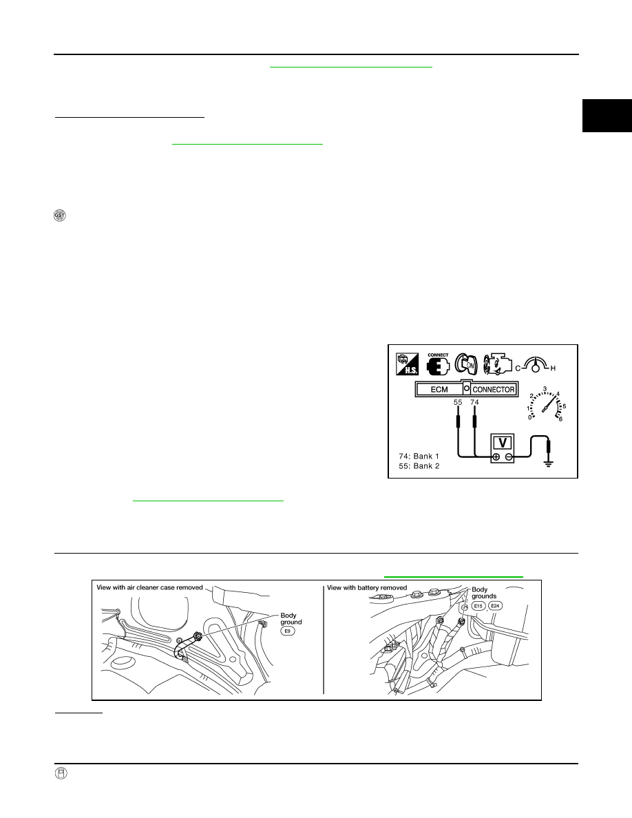
7.
Set voltmeter probes between ECM terminal 74 [HO2S2 (B1) signal] or 55 [HO2S2 (B2) signal] and
ground.
8.
Check the voltage when revving up to 4,000 rpm under no load
at least 10 times.
(Depress and release accelerator pedal as soon as possible.)
A change of voltage should be more than 0.8 V for 1 second
during this procedure.
If the voltage can be confirmed in step 6, step 7 is not nec-
essary.
9.
Keep vehicle at idling for 10 minutes, then check the voltage. Or
check the voltage when coasting from 80 km/h (50 MPH) in D
position with “OD” OFF (A/T), 5th gear position (M/T).
A change of voltage should be more than 0.8 V for 1 second
during this procedure.
10. If NG, go to
Diagnosis Procedure
INFOID:0000000005273603
1.
CHECK GROUND CONNECTIONS
1.
Turn ignition switch OFF.
2.
Loosen and retighten three ground screws on the body. Refer to
OK or NG
OK
>> GO TO 2.
NG
>> Repair or replace ground connections.
2.
CLEAR THE SELF-LEARNING DATA
With CONSULT-III
PBIB1607E
BBIA0539E