Nissan Frontier D40. Manual - part 470


  Index      Nissan     Nissan Frontier D40 (2010 year) - Service and Repair Manual


Search            


Content   ..  468  469  470  471   ..


Nissan Frontier D40. Manual - part 470


P0102, P0103 MAF SENSOR

EC-571

< COMPONENT DIAGNOSIS >

[VQ40DE]

C

D

E

F

G

H

I

J

K

L

M

A

EC

N

P

O

P0102, P0103 MAF SENSOR

Component Description

INFOID:0000000005273531

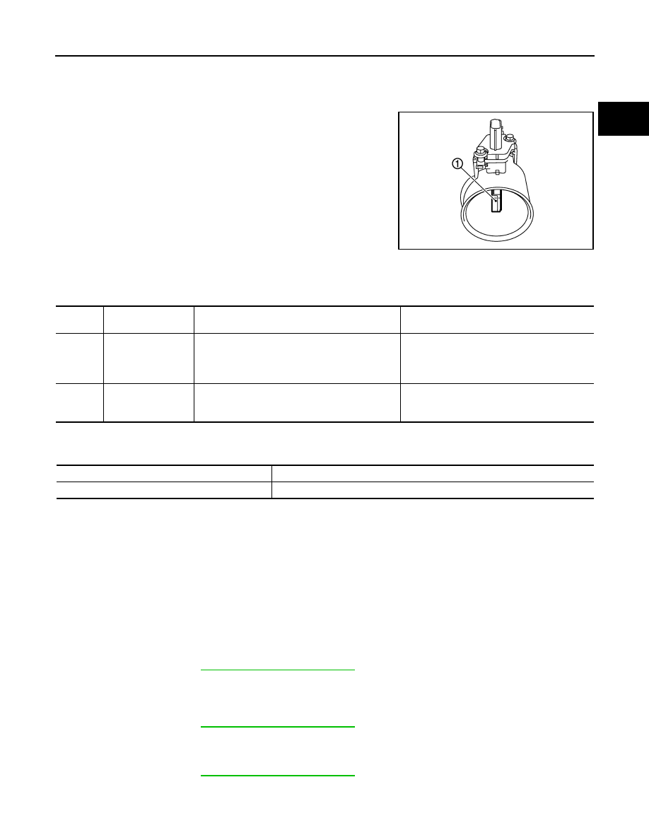
The mass air flow sensor (1) is placed in the stream of intake air. It
measures the intake flow rate by measuring a part of the entire
intake flow. The mass air flow sensor controls the temperature of the
hot wire to a certain amount. The heat generated by the hot wire is
reduced as the intake air flows around it. The more air, the greater
the heat loss.
Therefore, the electric current is supplied to hot wire is changed to
maintain the temperature of the hot wire as air flow increases. The
ECM detects the air flow by means of this current change.

On Board Diagnosis Logic

INFOID:0000000005273532

These self-diagnoses have the one trip detection logic.

FAIL-SAFE MODE

When the malfunction is detected, the ECM enters fail-safe mode and the MIL illuminates.

DTC Confirmation Procedure

INFOID:0000000005273533

NOTE:
If DTC Confirmation Procedure has been previously conducted, always perform the following before conduct-
ing the next step.

1.

Turn ignition switch OFF and wait at least 10 seconds.

2.

Turn ignition switch ON.

3.

Turn ignition switch OFF and wait at least 10 seconds.

PROCEDURE FOR DTC P0102

1.

Start engine and wait at least 5 seconds.

2.

Check DTC.

3.

If DTC is detected, go to 

EC-572, "Diagnosis Procedure"

.

PROCEDURE FOR DTC P0103

1.

Turn ignition switch ON and wait at least 5 seconds.

2.

Check DTC.

3.

If DTC is detected, go to 

EC-572, "Diagnosis Procedure"

.

If DTC is not detected, go to next step.

4.

Start engine and wait at least 5 seconds.

5.

Check DTC.

6.

If DTC is detected, go to 

EC-572, "Diagnosis Procedure"

.

PBIA9559J

DTC No.

Trouble diagnosis 

name

DTC detecting condition

Possible cause

P0102
0102

Mass air flow sensor 
circuit low input

An excessively low voltage from the sensor is sent 
to ECM.

• Harness or connectors

(The sensor circuit is open or shorted.)

• Intake air leaks
• Mass air flow sensor

P0103
0103

Mass air flow sensor 
circuit high input

An excessively high voltage from the sensor is 
sent to ECM.

• Harness or connectors

(The sensor circuit is open or shorted.)

• Mass air flow sensor

Detected items

Engine operating condition in fail-safe mode

Mass air flow sensor circuit

Engine speed will not rise more than 2,400 rpm due to the fuel cut.

EC-572

< COMPONENT DIAGNOSIS >

[VQ40DE]

P0102, P0103 MAF SENSOR

Diagnosis Procedure

INFOID:0000000005273534

1.

INSPECTION START

Which malfunction (P0102 or P0103) is duplicated?

P0102 or P0103

P0102 >> GO TO 2.
P0103 >> GO TO 3.

2.

CHECK INTAKE SYSTEM

Check the following for connection.
• Air duct
• Vacuum hoses
• Intake air passage between air duct and intake manifold
OK or NG

OK

>> GO TO 3.

NG

>> Reconnect the parts.

3.

CHECK GROUND CONNECTIONS

1.

Turn ignition switch OFF.

2.

Loosen and retighten three ground screws on the body. Refer to 

EC-549, "Ground Inspection"

.

OK or NG

OK

>> GO TO 4.

NG

>> Repair or replace ground connections.

4.

CHECK MAF SENSOR POWER SUPPLY CIRCUIT

1.

Disconnect mass air flow (MAF) sensor harness connector.

2.

Turn ignition switch ON.

BBIA0539E

BBIA0541E

P0102, P0103 MAF SENSOR

EC-573

< COMPONENT DIAGNOSIS >

[VQ40DE]

C

D

E

F

G

H

I

J

K

L

M

A

EC

N

P

O

3.

Check voltage between MAF sensor terminal 2 and ground with
CONSULT-III or tester.

OK or NG

OK

>> GO TO 6.

NG

>> GO TO 5.

5.

DETECT MALFUNCTIONING PART

Check the following.
• Harness connectors E2, F32
• Harness for open or short between IPDM E/R and mass air flow sensor
• Harness for open or short between mass air flow sensor and ECM

>> Repair open circuit or short to ground or short to power in harness or connectors.

6.

CHECK MAF SENSOR GROUND CIRCUIT FOR OPEN AND SHORT

1.

Turn ignition switch OFF.

2.

Disconnect ECM harness connector.

3.

Check harness continuity between MAF sensor terminal 3 and ECM terminal 67.
Refer to Wiring Diagram.

4.

Also check harness for short to ground and short to power.

OK or NG

OK

>> GO TO 7.

NG

>> Repair open circuit or short to ground or short to power in harness or connectors.

7.

CHECK MAF SENSOR INPUT SIGNAL CIRCUIT FOR OPEN AND SHORT

1.

Check harness continuity between MAF sensor terminal 4 and ECM terminal 51.
Refer to Wiring Diagram.

2.

Also check harness for short to ground and short to power.

OK or NG

OK

>> GO TO 8.

NG

>> Repair open circuit or short to ground or short to power in harness or connectors.

8.

CHECK MASS AIR FLOW SENSOR

Refer to 

EC-569, "Component Inspection"

.

OK or NG

OK

>> GO TO 9.

NG

>> Replace mass air flow sensor.

9.

CHECK INTERMITTENT INCIDENT

Refer to 

GI-46, "Intermittent Incident"

.

>> INSPECTION END

Component Inspection

INFOID:0000000005273535

MASS AIR FLOW SENSOR

Voltage: Battery voltage

PBIB1168E

Continuity should exist.

Continuity should exist.

EC-574

< COMPONENT DIAGNOSIS >

[VQ40DE]

P0102, P0103 MAF SENSOR

 With CONSULT-III

1.

Reconnect all harness connectors disconnected.

2.

Start engine and warm it up to normal operating temperature.

3.

Connect CONSULT-III and select “DATA MONITOR” mode.

4.

Select “MAS A/F SE-B1” and check indication under the following conditions.

*: Check for linear voltage rise in response to engine being increased to about 4,000 rpm.

5.

If the voltage is out of specification, proceed the following.

a.

Check for the cause of uneven air flow through mass air flow sensor. Refer to following.
• Crushed air ducts
• Malfunctioning seal of air cleaner element
• Uneven dirt of air cleaner element
• Improper specification of intake air system parts

b.

If NG, repair or replace malfunctioning part and perform step 2 to 4 again.
If OK, go to next step.

6.

Turn ignition switch OFF.

7.

Disconnect mass air flow sensor harness connector and reconnect it again.

8.

Perform step 2 to 4 again.

9.

If NG, clean or replace mass air flow sensor.

 Without CONSULT-III

1.

Reconnect all harness connectors disconnected.

2.

Start engine and warm it up to normal operating temperature.

3.

Check voltage between ECM terminal 51 (Mass air flow sensor
signal) and ground.

*: Check for linear voltage rise in response to engine being increased to about 4,000 rpm.

4.

If the voltage is out of specification, proceed the following.

a.

Check for the cause of uneven air flow through mass air flow sensor. Refer to following.
• Crushed air ducts
• Malfunctioning seal of air cleaner element
• Uneven dirt of air cleaner element
• Improper specification of intake air system parts

b.

If NG, repair or replace malfunctioning part and perform step 2 to 3 again.
If OK, go to next step.

5.

Turn ignition switch OFF.

6.

Disconnect mass air flow sensor harness connector and reconnect it again.

7.

Perform step 2 and 3 again.

Condition

MAS A/F SE-B1 (V)

Ignition switch ON (Engine stopped.)

Approx. 0.4

Idle (Engine is warmed-up to normal 
operating temperature.)

0.9 - 1.2

2,500 rpm (Engine is warmed-up to 
normal operating temperature.)

1.5 - 1.8

Idle to about 4,000 rpm

0.9 - 1.2 to Approx. 2.4*

Condition

Voltage V

Ignition switch ON (Engine stopped.)

Approx. 0.4

Idle (Engine is warmed-up to normal 
operating temperature.)

0.9 - 1.2

2,500 rpm (Engine is warmed-up to 
normal operating temperature.)

1.5 - 1.8

Idle to about 4,000 rpm

0.9 - 1.2 to Approx. 2.4*

PBIB1106E


Content   ..  468  469  470  471   ..