Nissan Frontier D40. Manual - part 458


  Index      Nissan     Nissan Frontier D40 (2010 year) - Service and Repair Manual


Search            


Content   ..  456  457  458  459   ..


Nissan Frontier D40. Manual - part 458


ON BOARD DIAGNOSTIC (OBD) SYSTEM

EC-523

< FUNCTION DIAGNOSIS >

[VQ40DE]

C

D

E

F

G

H

I

J

K

L

M

A

EC

N

P

O

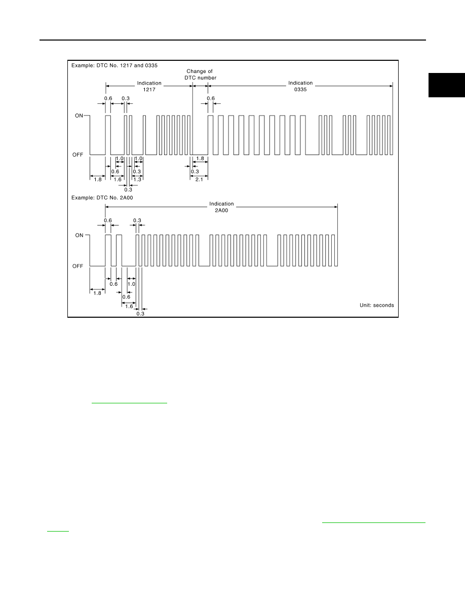
tified codes can be identified by using the CONSULT-III or GST. A DTC will be used as an example for how to
read a code.

A particular trouble code can be identified by the number of four-digit numeral flashes. The “zero” is indicated
by the number of ten flashes. The “A” is indicated by the number of eleven flash. The length of time the
1,000th-digit numeral flashes on and off is 1.2 seconds consisting of an ON (0.6-seconds) - OFF (0.6-sec-
onds) cycle.
The 100th-digit numeral and lower digit numerals consist of a 0.3-seconds ON and 0.3-seconds OFF cycle.
A change from one digit numeral to another occurs at an interval of 1.0-second OFF. In other words, the later
numeral appears on the display 1.3 seconds after the former numeral has disappeared.
A change from one trouble code to another occurs at an interval of 1.8-seconds OFF.
In this way, all the detected malfunctions are classified by their DTC numbers. The DTC 0000 refers to no mal-
function. (See 

EC-919, "DTC Index"

)

How to Erase Diagnostic Test Mode II (Self-diagnostic Results)

The DTC can be erased from the back up memory in the ECM by depressing accelerator pedal. Refer to "How
to Set Diagnostic Test Mode II (Self-diagnostic Results)".
• If the battery is disconnected, the DTC will be lost from the backup memory within 24 hours.
• Be careful not to erase the saved memory before starting trouble diagnoses.

OBD System Operation Chart

INFOID:0000000005273489

RELATIONSHIP BETWEEN MIL, 1ST TRIP DTC, DTC, AND DETECTABLE ITEMS

• When a malfunction is detected for the first time, the 1st trip DTC and the 1st trip freeze frame data are

saved in the ECM memory.

• When the same malfunction is detected in two consecutive trips, the DTC and the freeze frame data are

saved in the ECM memory, and the MIL will come on. For details, refer to 

EC-500, "Two Trip Detection

Logic"

.

• The MIL will go off after the vehicle is driven 3 times with no malfunction. The drive is counted only when the

recorded driving pattern is met (as saved in the ECM). If another malfunction occurs while counting, the
counter will reset.

• The DTC and the freeze frame data will be saved until the vehicle is driven 40 times (driving pattern A) with-

out the same malfunction recurring (except for Misfire and Fuel Injection System). For Misfire and Fuel Injec-

PBIB3005E

EC-524

< FUNCTION DIAGNOSIS >

[VQ40DE]

ON BOARD DIAGNOSTIC (OBD) SYSTEM

tion System, the DTC and freeze frame data will be saved until the vehicle is driven 80 times (driving pattern
C) without the same malfunction recurring. The “TIME” in “SELF-DIAGNOSTIC RESULTS” mode of CON-
SULT-III will count the number of times the vehicle is driven.

• The 1st trip DTC is not displayed when the self-diagnosis results in OK for the 2nd trip.

SUMMARY CHART

For details about patterns B and C under “Fuel Injection System” and “Misfire”, see "EXPLANATION FOR DRIVING PATTERNS FOR
“MISFIRE <EXHAUST QUALITY DETERIORATION>”, “FUEL INJECTION SYSTEM”".

For details about patterns A and B under Other, see "EXPLANATION FOR DRIVING PATTERNS  FOR “MISFIRE <EXHAUST QUALITY
DETERIORATION>”, “FUEL INJECTION SYSTEM”".

*1: Clear timing is at the moment OK is detected.

*2: Clear timing is when the same malfunction is detected in the 2nd trip.

RELATIONSHIP BETWEEN MIL, DTC, 1ST TRIP DTC AND DRIVING PATTERNS FOR “MISFIRE ”
<EXHAUST QUALITY DETERIORATION>, “FUEL INJECTION SYSTEM”

Items

Fuel Injection System

Misfire

Other

MIL (turns off)

3 (pattern B)

3 (pattern B)

3 (pattern B)

DTC, Freeze Frame Data (no 
display)

80 (pattern C)

80 (pattern C)

40 (pattern A)

1st Trip DTC (clear)

1 (pattern C), *1

1 (pattern C), *1

1 (pattern B)

1st Trip Freeze Frame Data 
(clear)

*1, *2

*1, *2

1 (pattern B)

ON BOARD DIAGNOSTIC (OBD) SYSTEM

EC-525

< FUNCTION DIAGNOSIS >

[VQ40DE]

C

D

E

F

G

H

I

J

K

L

M

A

EC

N

P

O

EXPLANATION FOR DRIVING PATTERNS FOR “MISFIRE <EXHAUST QUALITY DETERIORA-
TION>”, “FUEL INJECTION SYSTEM”

<Driving Pattern B>

Driving pattern B means the vehicle operation as par the following:

*1: When the same malfunction is de-

tected in two consecutive trips, MIL 
will illuminate.

*2: MIL will turn off after vehicle is driven 

3 times (pattern B) without any mal-
functions.

*3: When the same malfunction is de-

tected in two consecutive trips, the 
DTC and the freeze frame data will be 
saved in ECM.

*4: The DTC and the freeze frame data 

will not be displayed any longer after 
vehicle is driven 80 times (pattern C) 
without the same malfunction. (The 
DTC and the freeze frame data still 
remain in ECM.)

*5: When a malfunction is detected for 

the first time, the 1st trip DTC and the 
1st trip freeze frame data will be 
saved in ECM.

*6: The 1st trip DTC and the 1st trip 

freeze frame data will be cleared at 
the moment OK is detected.

*7: When the same malfunction is de-

tected in the 2nd trip, the 1st trip 
freeze frame data will be cleared.

*8: 1st trip DTC will be cleared when ve-

hicle is driven once (pattern C) with-
out the same malfunction after DTC 
is saved in ECM.

JMBIA1417GB

EC-526

< FUNCTION DIAGNOSIS >

[VQ40DE]

ON BOARD DIAGNOSTIC (OBD) SYSTEM

All components and systems should be monitored at least once by the OBD system.
• The B counter will be cleared when the malfunction is detected once regardless of the driving pattern.
• The B counter will be counted up when driving pattern B is satisfied without any malfunction.
• The MIL will turn off when the B counter reaches 3. (*2 in “OBD SYSTEM OPERATION CHART”)

<Driving Pattern C>

Driving pattern C means operating vehicle as par the following:
The following conditions should be satisfied at the same time:
Engine speed: (Engine speed in the freeze frame data) 

±

375 rpm

Calculated load value: (Calculated load value in the freeze frame data) x (1

±

0.1) [%]

Engine coolant temperature (T) condition:
• When the freeze frame data shows lower than 70

°

C (158

°

F), T should be lower than 70

°

C (158

°

F).

• When the freeze frame data shows higher than or equal to 70

°

C (158

°

F), T should be higher than or equal to

70

°

C (158

°

F).

Example:
If the saved freeze frame data is as par the following:
Engine speed: 850 rpm, Calculated load value: 30%, Engine coolant temperature: 80

°

C (176

°

F)

To be satisfied with driving pattern C, the vehicle should run under the following conditions:
Engine speed: 475 - 1,225 rpm, Calculated load value: 27 - 33%, Engine coolant temperature: more than 70

°

C

(158

°

F)

• The C counter will be cleared when the malfunction is detected regardless of vehicle conditions above.
• The C counter will be counted up when vehicle conditions above are satisfied without the same malfunction.
• The DTC will not be displayed after C counter reaches 80.
• The 1st trip DTC will be cleared when C counter is counted once without the same malfunction after DTC is

saved in ECM.

RELATIONSHIP BETWEEN MIL, DTC, 1ST TRIP DTC AND DRIVING PATTERNS EXCEPT FOR
“MISFIRE <EXHAUST QUALITY DETERIORATION>”, “FUEL INJECTION SYSTEM”


Content   ..  456  457  458  459   ..