Nissan Frontier D40. Manual - part 442
EVAP CANISTER
EC-459
< ON-VEHICLE REPAIR >
[QR25DE]
C
D
E
F
G
H
I
J
K
L
M
A
EC
N
P
O
ON-VEHICLE REPAIR
EVAP CANISTER
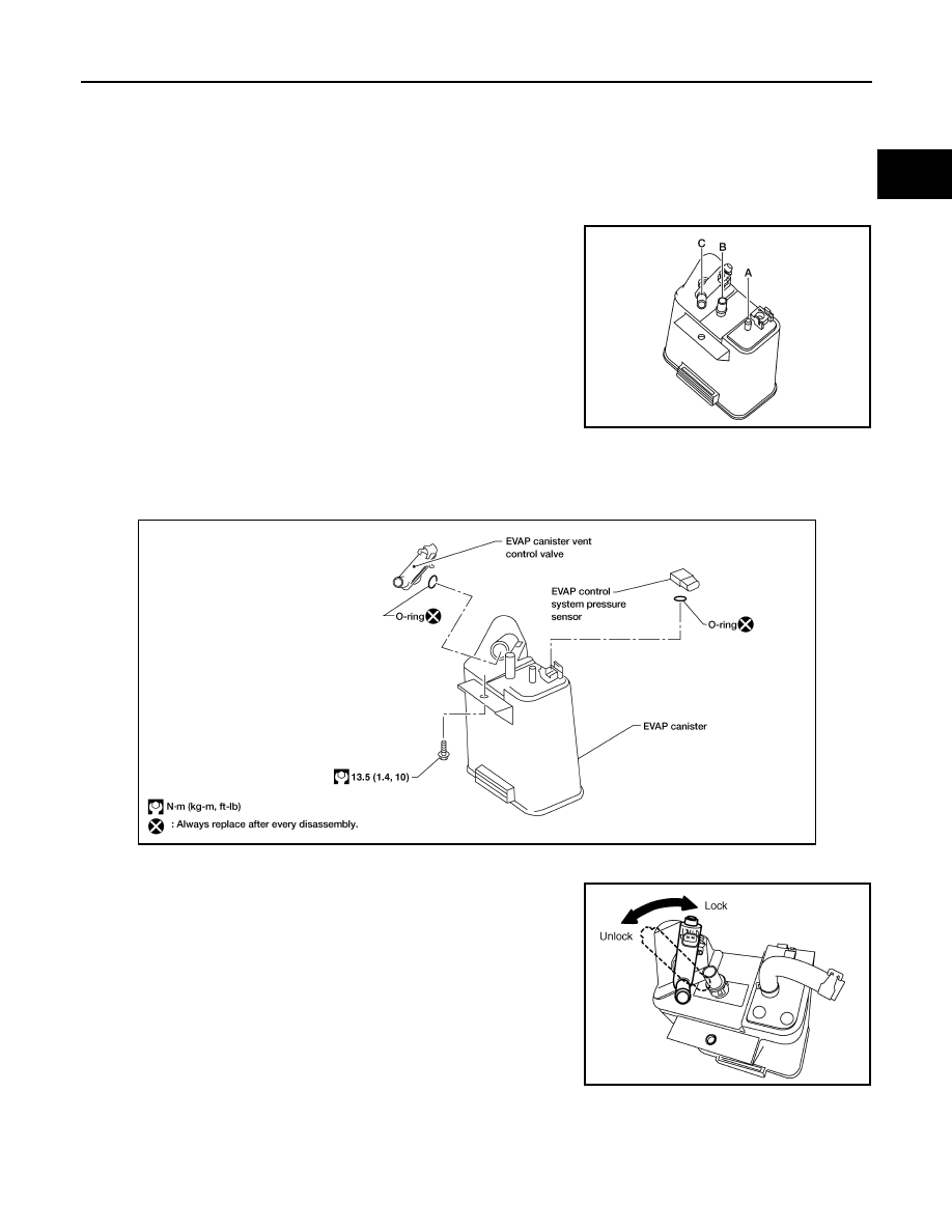
Component Inspection
INFOID:0000000005273448
EVAP CANISTER
Check EVAP canister as follows:
1.
Block port B.
2.
Blow air into port A and check that it flows freely out of port C.
3.
Release blocked port B.
4.
Apply vacuum pressure to port B and check that vacuum pres-
sure exists at the ports A and C.
5.
Block port A and B.
6.
Apply pressure to port C and check that there is no leakage.
Removal and Installation
INFOID:0000000005273449
EVAP CANISTER
Tighten EVAP canister as shown in the figure.
EVAP CANISTER VENT CONTROL VALVE
1.
Turn EVAP canister vent control valve counterclockwise.
2.
Remove the EVAP canister vent control valve.
Do not reuse the O-ring, replace it with a new one.
BBIA0639E
BBIA0566E
BBIA0567E