Nissan Frontier D40. Manual - part 421


  Index      Nissan     Nissan Frontier D40 (2010 year) - Service and Repair Manual


Search            


Content   ..  419  420  421  422   ..


Nissan Frontier D40. Manual - part 421


FUEL INJECTOR

EC-375

< COMPONENT DIAGNOSIS >

[QR25DE]

C

D

E

F

G

H

I

J

K

L

M

A

EC

N

P

O

FUEL INJECTOR

Component Description

INFOID:0000000005273415

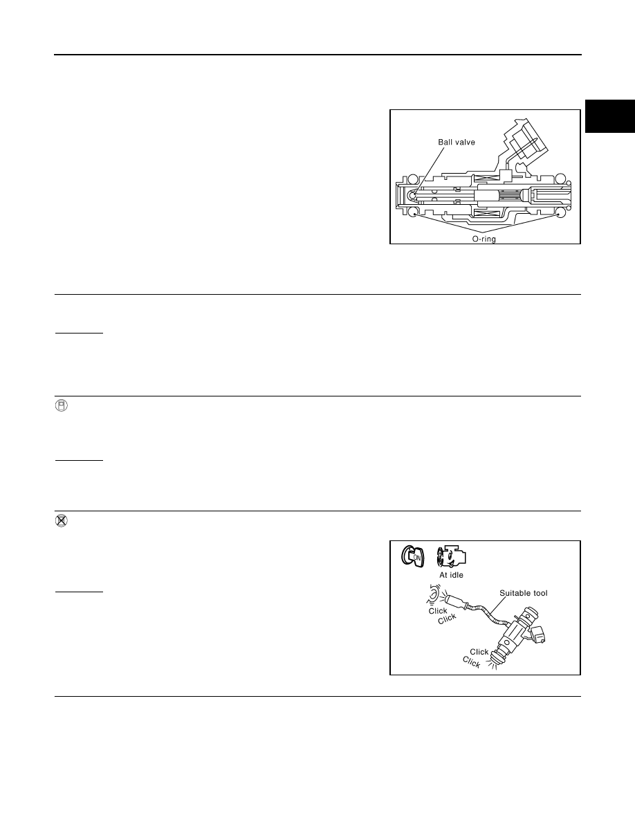
The fuel injector is a small, precise solenoid valve. When the ECM
supplies a ground to the fuel injector circuit, the coil in the fuel injec-
tor is energized. The energized coil pulls the ball valve back and
allows fuel to flow through the fuel injector into the intake manifold.
The amount of fuel injected depends upon the injection pulse dura-
tion. Pulse duration is the length of time the fuel injector remains
open. The ECM controls the injection pulse duration based on
engine fuel needs.

Diagnosis Procedure

INFOID:0000000005273416

1.

INSPECTION START

Turn ignition switch to START.
Is any cylinder ignited?

Yes or No

Yes (With CONSULT-III)>>GO TO 2.
Yes (Without CONSULT-III)>>GO TO 3.
No

>> GO TO 4.

2.

CHECK OVERALL FUNCTION

 With CONSULT-III

1.

Start engine.

2.

Perform “POWER BALANCE” in “ACTIVE TEST” mode with CONSULT-III.

3.

Make sure that each circuit produces a momentary engine speed drop.

OK or NG

OK

>> INSPECTION END

NG

>> GO TO 4.

3.

CHECK FUNCTION OF FUEL INJECTOR

 Without CONSULT-III

1.

Start engine.

2.

Listen to each fuel injector operating sound.

OK or NG

OK

>> INSPECTION END

NG

>> GO TO 4.

4.

CHECK FUEL INJECTOR POWER SUPPLY CIRCUIT

1.

Turn ignition switch OFF.

SEF375Z

Clicking noise should exist.

PBIB1986E

EC-376

< COMPONENT DIAGNOSIS >

[QR25DE]

FUEL INJECTOR

2.

Disconnect fuel injector harness connector.

3.

Turn ignition switch ON.

4.

Check voltage between fuel injector terminal 1 and ground with
CONSULT-III or tester.

OK or NG

OK

>> GO TO 6.

NG

>> GO TO 5.

5.

DETECT MALFUNCTIONING PART

Check the following.
• Harness connectors E2, F32
• Harness connectors F45, F210
• IPDM E/R harness connector E119
• 15A fuse (No.55)
• Harness for open or short between fuel injector and fuse

>> Repair harness or connectors.

6.

CHECK FUEL INJECTOR OUTPUT SIGNAL CIRCUIT FOR OPEN AND SHORT

1.

Turn ignition switch OFF.

2.

Disconnect ECM harness connector.

3.

Check harness continuity between fuel injector terminal 2 and ECM terminals 22, 23, 41, 42. 
Refer to Wiring Diagram.

4.

Also check harness for short to ground and short to power.

OK or NG

OK

>> GO TO 8.

NG

>> GO TO 7.

7.

DETECT MALFUNCTIONING PART

Check the following.
• Harness connectors F210, F45
• Harness for open or short between fuel injector and ECM

>> Repair open circuit, short to ground or short to power in harness or connectors.

8.

CHECK FUEL INJECTOR

Refer to 

EC-377, "Component Inspection"

.

OK or NG

BBIA0625E

Voltage: Battery voltage

PBIB0582E

Continuity should exist.

FUEL INJECTOR

EC-377

< COMPONENT DIAGNOSIS >

[QR25DE]

C

D

E

F

G

H

I

J

K

L

M

A

EC

N

P

O

OK

>> GO TO 9.

NG

>> Replace fuel injector.

9.

CHECK INTERMITTENT INCIDENT

Refer to 

GI-46, "Intermittent Incident"

.

>> INSPECTION END

Component Inspection

INFOID:0000000005273417

FUEL INJECTOR

1.

Disconnect fuel injector harness connector.

2.

Check resistance between terminals as shown in the figure.

Resistance: 11.1 - 14.3

 [at 10 - 60

°

C (50 - 140

°

F)]

PBIB1727E

EC-378

< COMPONENT DIAGNOSIS >

[QR25DE]

FUEL PUMP

FUEL PUMP

Description

INFOID:0000000005273418

SYSTEM DESCRIPTION

*: ECM determines the start signal status by the signals of engine speed and battery voltage.

The ECM activates the fuel pump for 1 second after the ignition switch is turned ON to improve engine start
ability. If the ECM receives a engine speed signal from the camshaft position sensor (PHASE), it knows that
the engine is rotating, and causes the pump to operate. If the engine speed signal is not received when the
ignition switch is ON, the engine stalls. The ECM stops pump operation and prevents battery discharging,
thereby improving safety. The ECM does not directly drive the fuel pump. It controls the ON/OFF fuel pump
relay, which in turn controls the fuel pump.

COMPONENT DESCRIPTION

A turbine type design fuel pump is used in the fuel tank.

Diagnosis Procedure

INFOID:0000000005273419

1.

CHECK OVERALL FUNCTION

1.

Turn ignition switch ON.

2.

Pinch fuel feed hose with two fingers.
Fuel pressure pulsation should be felt on the fuel feed hose
for 1 second after ignition switch is turned ON.

OK or NG

OK

>> INSPECTION END

NG

>> GO TO 2.

2.

CHECK FUEL PUMP POWER SUPPLY CIRCUIT-I

1.

Turn ignition switch OFF.

2.

Disconnect ECM harness connector.

3.

Turn ignition switch ON.

Sensor

Input signal to ECM

ECM function

Actuator

Crankshaft position sensor (POS)
Camshaft position sensor (PHASE)

Engine speed*

Fuel pump control

Fuel pump relay

Battery

Battery voltage*

Condition

Fuel pump operation

Ignition switch is turned to ON

Operates for 1 second.

Engine running and cranking

Operates.

When engine is stopped

Stops in 1.5 seconds.

Except as shown above

Stops.

BBIA0529E

BBIA0626E


Content   ..  419  420  421  422   ..