Nissan Frontier D40. Manual - part 419


  Index      Nissan     Nissan Frontier D40 (2010 year) - Service and Repair Manual


Search            


Content   ..  417  418  419  420   ..


Nissan Frontier D40. Manual - part 419


P2A00 A/F SENSOR 1

EC-367

< COMPONENT DIAGNOSIS >

[QR25DE]

C

D

E

F

G

H

I

J

K

L

M

A

EC

N

P

O

Replace air fuel ratio (A/F) sensor 1.

CAUTION:

• Discard any air fuel ratio (A/F) sensor which has been dropped from a height of more than 0.5 m

(19.7 in) onto a hard surface such as a concrete floor; use a new one.

• Before installing new air fuel ratio (A/F) sensor, clean exhaust system threads using Heated Oxygen

Sensor Thread Cleaner [commercial service tool (J-43897-18 or J-43897-12)] and approved anti-seize
lubricant (commercial service tool).

>> GO TO 12.

12.

CONFIRM A/F ADJUSTMENT DATA

1.

Turn ignition switch ON.

2.

Select “A/F ADJ-B1” in “DATA MONITOR” mode with CONSULT-III.

3.

Make sure that “0.000” is displayed on CONSULT-III screen.

OK or NG

OK

>> INSPECTION END.

NG

>> GO TO 13.

13.

CLEAR THE SELF-LEARNING DATA

 With CONSULT-III

1.

Start engine and warm it up to normal operating temperature.

2.

Select “SELF-LEARNING CONT” in “WORK SUPPORT” mode with CONSULT-III.

3.

Clear the self-learning control coefficient by touching “CLEAR”.

 Without CONSULT-III

1.

Start engine and warm it up to normal operating temperature.

2.

Turn ignition switch OFF.

3.

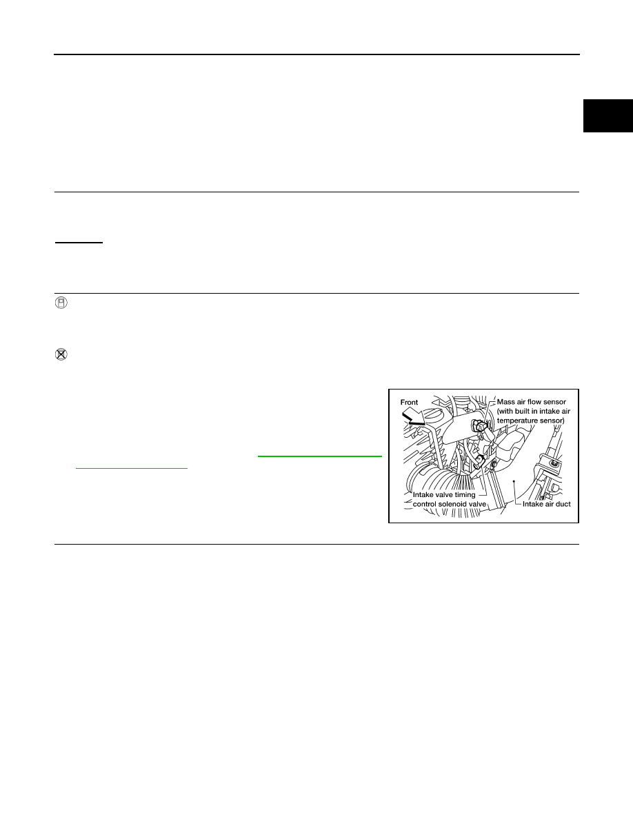
Disconnect mass air flow sensor harness connector.

4.

Restart engine and let it idle for at least 5 seconds.

5.

Stop engine and reconnect mass air flow sensor harness con-
nector.

6.

Make sure DTC P0102 is displayed.

7.

Erase the DTC memory. Refer to 

EC-47, "Emission-related

Diagnostic Information"

.

8.

Make sure DTC P0000 is displayed.

>> GO TO 14.

14.

CONFIRM A/F ADJUSTMENT DATA

1.

Turn ignition switch OFF and then ON.

2.

Select “A/F ADJ-B1” in “DATA MONITOR” mode with CONSULT-III.

3.

Make sure that “0.000” is displayed on CONSULT-III screen.

>> INSPECTION END

BBIA0622E

EC-368

< COMPONENT DIAGNOSIS >

[QR25DE]

ASCD BRAKE SWITCH

ASCD BRAKE SWITCH

Component Description

INFOID:0000000005273408

When depress on the brake pedal, ASCD brake switch is turned
OFF and stop lamp switch is turned ON. ECM detects the state of
the brake pedal by this those two types of input (ON/OFF signal)
Refer to 

CCS-2

 for the ASCD function.

Diagnosis Procedure

INFOID:0000000005273409

A/T MODELS

1.

CHECK OVERALL FUNCTION-I

 With CONSULT-III

1.

Turn ignition switch ON.

2.

Select “BRAKE SW1” in “DATA MONITOR” mode with CONSULT-III.

3.

Check “BRAKE SW1” indication under the following conditions.

 Without CONSULT-III

1.

Turn ignition switch ON.

2.

Check voltage between ECM terminal 108 and ground under the
following conditions.

OK or NG

OK

>> INSPECTION END.

NG

>> GO TO 2.

2.

CHECK ASCD BRAKE SWITCH POWER SUPPLY CIRCUIT

1.

Turn ignition switch OFF.

BBIA0560E

CONDITION

INDICATION

Brake pedal: Slightly depressed

OFF

Brake pedal: Fully released

ON

CONDITION

VOLTAGE

Brake pedal: Slightly depressed

Approximately 0V

Brake pedal: Fully released

Battery voltage

MBIB0061E

ASCD BRAKE SWITCH

EC-369

< COMPONENT DIAGNOSIS >

[QR25DE]

C

D

E

F

G

H

I

J

K

L

M

A

EC

N

P

O

2.

Disconnect ASCD brake switch harness connector.

3.

Turn ignition switch ON.

4.

Check voltage between ASCD brake switch terminal 1 and
ground with CONSULT-III or tester.

OK or NG

OK

>> GO TO 4.

NG

>> GO TO 3.

3.

DETECT MALFUNCTIONING PART

Check the following.
• Fuse block (J/B) connector E160
• 10A fuse (No.12)
• Harness for open or short between ASCD brake switch and fuse

>> Repair open circuit or short to ground in harness or connectors.

4.

CHECK ASCD BRAKE SWITCH INPUT SIGNAL CIRCUIT FOR OPEN AND SHORT

1.

Turn ignition switch OFF.

2.

Disconnect ECM harness connector.

3.

Check harness continuity between ECM terminal 108 and ASCD brake switch terminal 2.
Refer to Wiring Diagram.

4.

Also check harness for short to ground and short to power.

OK or NG

OK

>> GO TO 5.

NG

>> Repair open circuit, short to ground or short to power in harness or connectors.

5.

CHECK ASCD BRAKE SWITCH

Refer to 

EC-372, "Component Inspection"

.

OK or NG

OK

>> GO TO 6.

NG

>> Replace ASCD brake switch.

6.

CHECK INTERMITTENT INCIDENT

Refer to 

GI-46, "Intermittent Incident"

.

>> INSPECTION END

M/T MODELS

1.

CHECK OVERALL FUNCTION-I

BBIA0560E

Voltage: Battery voltage

PBIB0857E

Continuity should exist.

EC-370

< COMPONENT DIAGNOSIS >

[QR25DE]

ASCD BRAKE SWITCH

 With CONSULT-III

1.

Turn ignition switch ON.

2.

Select “BRAKE SW1” in “DATA MONITOR” mode with CONSULT-III.

3.

Check “BRAKE SW1” indication under the following conditions.

 Without CONSULT-III

1.

Turn ignition switch ON.

2.

Check voltage between ECM terminal 108 and ground under the
following conditions.

OK or NG

OK

>> INSPECTION END.

NG

>> GO TO 2.

2.

CHECK ASCD BRAKE SWITCH CIRCUIT

1.

Turn ignition switch OFF.

2.

Disconnect ASCD clutch switch harness connector.

3.

Turn ignition switch ON.

4.

Check voltage between ASCD clutch switch terminal 1 and
ground under the following conditions with CONSULT-III or
tester.

OK or NG

OK 

>> GO TO 7.

NG

>> GO TO 3.

3.

CHECK ASCD BRAKE SWITCH POWER SUPPLY CIRCUIT

1.

Turn ignition switch OFF.

CONDITION

INDICATION

Brake pedal and/or clutch pedal: Slightly depressed

OFF

Brake pedal and clutch pedal: Fully released

ON

CONDITION

VOLTAGE

Brake pedal and/or clutch pedal: Slightly depressed

Approximately 0V

Brake pedal and clutch pedal: Fully released

Battery voltage

MBIB0061E

BBIA0624E

CONDITION

VOLTAGE

Brake pedal: Fully released

Battery voltage

Brake pedal: Slightly depressed

Approx. 0V

PBIB0799E


Content   ..  417  418  419  420   ..