Nissan Frontier D40. Manual - part 410
P1574 ASCD VEHICLE SPEED SENSOR
EC-331
< COMPONENT DIAGNOSIS >
[QR25DE]
C
D
E
F
G
H
I
J
K
L
M
A
EC
N
P
O
P1574 ASCD VEHICLE SPEED SENSOR
Component Description
INFOID:0000000005273354
The ECM receives two vehicle speed sensor signals via CAN communication line. One is sent from combina-
tion meter, and the other is from TCM (Transmission control module). The ECM uses these signals for ASCD
control. Refer to
for ASCD functions.
On Board Diagnosis Logic
INFOID:0000000005273355
This self-diagnosis has the one trip detection logic.
The MIL will not light up for this self-diagnosis.
NOTE:
• If DTC P1574 is displayed with DTC UXXXX, first perform the trouble diagnosis for DTC UXXXX.
Refer to
.
• If DTC P1574 is displayed with DTC P0607, first perform the trouble diagnosis for DTC P0607. Refer
.
• If DTC P1574 is displayed with DTC P0500, first perform the trouble diagnosis for DTC P0500. Refer
.
• If DTC P1574 is displayed with DTC P0605, first perform the trouble diagnosis for DTC P0605. Refer
.
DTC Confirmation Procedure
INFOID:0000000005273356
CAUTION:
Always drive vehicle at a safe speed.
NOTE:
If DTC Confirmation Procedure has been previously conducted, always turn ignition switch OFF and wait at
least 10 seconds before conducting the next test.
TESTING CONDITION:
Step 3 may be conducted with the drive wheels lifted in the shop or by driving the vehicle. If a road test
is expected to be easier, it is unnecessary to lift the vehicle.
WITH CONSULT-III
1.
Start engine.
2.
Drive the vehicle at more than 40 km/h (25MPH).
3.
Check DTC.
4.
If DTC is detected, go to
.
WITH GST
Follow the procedure “WITH CONSULT-III” above.
Diagnosis Procedure
INFOID:0000000005273357
1.
CHECK DTC WITH TCM
Check DTC with TCM. Refer to
TM-151, "CONSULT-III Function (TRANSMISSION)"
.
OK or NG
OK
>> GO TO 2.
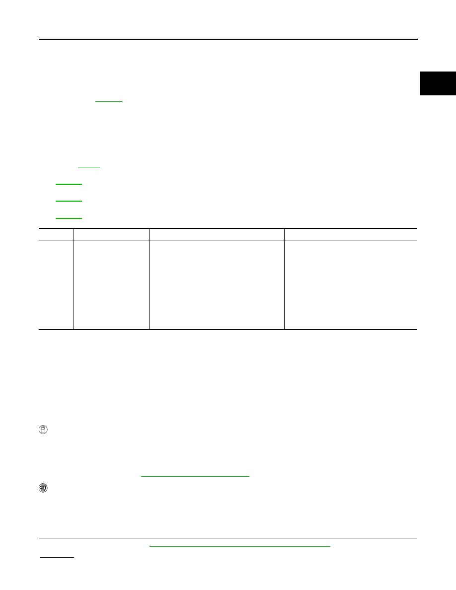
DTC No.
Trouble diagnosis name
DTC detecting condition
Possible cause
P1574
1574
ASCD vehicle speed
sensor
ECM detects a difference between two vehicle
speed signals is out of the specified range.
• Harness or connectors
(The CAN communication line is open or
shorted.)
• Harness or connectors
(The combination meter circuit is open or
shorted.)
• Combination meter
• Wheel sensor
• ABS actuator and electric unit (control unit)
• TCM (A/T models)
• ECM