Nissan Frontier D40. Manual - part 408
P1572 ASCD BRAKE SWITCH
EC-323
< COMPONENT DIAGNOSIS >
[QR25DE]
C
D
E
F
G
H
I
J
K
L
M
A
EC
N
P
O
3.
Press MAIN switch and make sure that CRUISE indicator lights up.
4.
Drive the vehicle for at least 5 consecutive seconds under the following condition.
5.
Check DTC.
6.
If DTC is detected, go to
.
If DTC is not detected, go to the following steps.
7.
Drive the vehicle for at least 5 consecutive seconds under the following condition.
8.
Check DTC.
9.
If DTC is detected, go to
.
WITH GST
Follow the procedure “WITH CONSULT-III” above.
Diagnosis Procedure
INFOID:0000000005273352
A/T MODELS
1.
CHECK OVERALL FUNCTION-I
With CONSULT-III
1.
Turn ignition switch ON.
2.
Select “BRAKE SW1” in “DATA MONITOR” mode with CONSULT-III.
3.
Check “BRAKE SW1” indication under the following conditions.
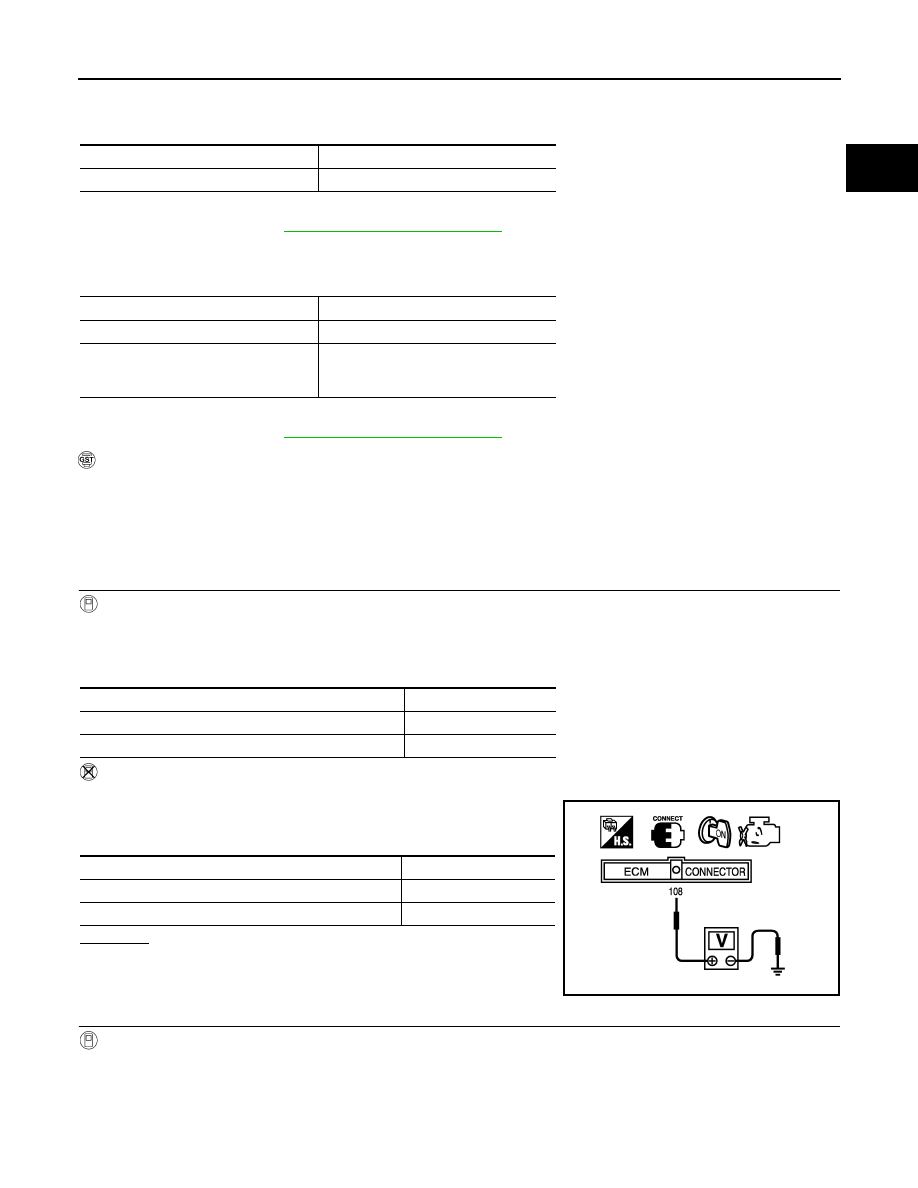
Without CONSULT-III
1.
Turn ignition switch ON.
2.
Check voltage between ECM terminal 108 and ground under the
following conditions.
OK or NG
OK
>> GO TO 2.
NG
>> GO TO 3.
2.
CHECK OVERALL FUNCTION-II
With CONSULT-III
Check “BRAKE SW2” indication in “DATA MONITOR” mode.
VHCL SPEED SE
More than 30 km/h (19 MPH)
Shift lever
Suitable position
VHCL SPEED SE
More than 30 km/h (19 MPH)
Shift lever
Suitable position
Driving location
Depress the brake pedal for more than 5
seconds so as not to come off from the
above-mentioned vehicle speed.
CONDITION
INDICATION
Brake pedal: Slightly depressed
OFF
Brake pedal: Fully released
ON
CONDITION
VOLTAGE
Brake pedal: Slightly depressed
Approximately 0V
Brake pedal: Fully released
Battery voltage
MBIB0061E