Nissan Frontier D40. Manual - part 378


  Index      Nissan     Nissan Frontier D40 (2010 year) - Service and Repair Manual


Search            


Content   ..  376  377  378  379   ..


Nissan Frontier D40. Manual - part 378


P0340 CMP SENSOR (PHASE)

EC-203

< COMPONENT DIAGNOSIS >

[QR25DE]

C

D

E

F

G

H

I

J

K

L

M

A

EC

N

P

O

Check the following.
• Harness connectors E2, F32
• Harness for open or short between camshaft position sensor (PHASE) and ECM
• Harness for open or short between camshaft position sensor (PHASE) and IPDM E/R

>> Repair open circuit, short to ground or short to power in harness or connectors.

5.

CHECK CMP SENSOR (PHASE) GROUND CIRCUIT FOR OPEN AND SHORT

1.

Turn ignition switch OFF.

2.

Check harness continuity between CMP sensor (PHASE) terminal 3 and ground.

3.

Also check harness for short to power.

OK or NG

OK

>> GO TO 7.

NG

>> GO TO 6.

6.

DETECT MALFUNCTIONING PART

Check the following.
• Harness connector E2, F32
• Harness for open or short between CMP sensor (PHASE) and ground.

>> Repair open circuit or short to power in harness or connectors.

7.

CHECK CMP SENSOR (PHASE) INPUT SIGNAL CIRCUIT FOR OPEN AND SHORT

1.

Disconnect ECM harness connector.

2.

Check harness continuity between ECM terminal 14 and CMP sensor (PHASE) terminal 2. 
Refer to Wiring Diagram.

3.

Also check harness for short to ground and short to power.

OK or NG

OK

>> GO TO 8.

NG

>> Repair open circuit, short to ground or short to power in harness or connectors.

8.

CHECK CAMSHAFT POSITION SENSOR (PHASE)

Refer to 

EC-204, "Component Inspection"

.

OK or NG

OK

>> GO TO 9.

NG

>> Replace camshaft position sensor (PHASE).

9.

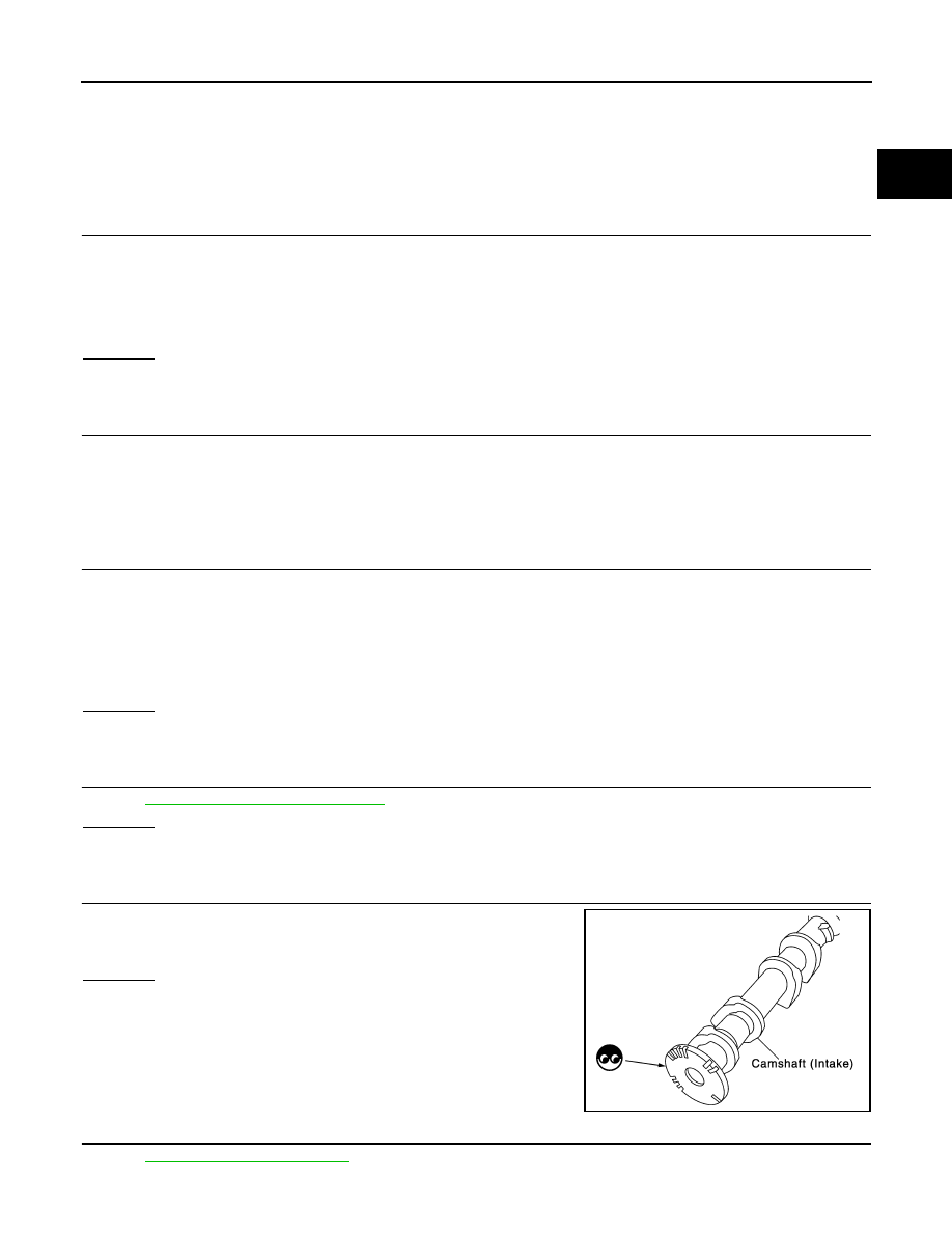
CHECK CAMSHAFT (INTAKE)

Check the following.
• Accumulation of debris to the signal plate of camshaft rear end
• Chipping signal plate of camshaft rear end

OK or NG

OK

>> GO TO 10.

NG

>> Remove debris and clean the signal plate of camshaft

rear end or replace camshaft.

10.

CHECK INTERMITTENT INCIDENT

Refer to 

GI-46, "Intermittent Incident"

.

Continuity should exist.

Continuity should exist.

PBIB0565E

EC-204

< COMPONENT DIAGNOSIS >

[QR25DE]

P0340 CMP SENSOR (PHASE)

>> INSPECTION END

Component Inspection

INFOID:0000000005273199

CAMSHAFT POSITION SENSOR (PHASE)

1.

Loosen the fixing bolt of the sensor.

2.

Disconnect camshaft position sensor (PHASE) harness connector.

3.

Remove the sensor.

4.

Visually check the sensor for chipping.

5.

Check resistance as shown in the figure.

PBIB0563E

Terminal No. (Polarity)

Resistance 

 [at 25

°

C (77

°

F)]

1 (+) - 2 (-)

Except 0 or 

1 (+) - 3 (-)

2 (+) - 3 (-)

PBIB0564E

P0420 THREE WAY CATALYST FUNCTION

EC-205

< COMPONENT DIAGNOSIS >

[QR25DE]

C

D

E

F

G

H

I

J

K

L

M

A

EC

N

P

O

P0420 THREE WAY CATALYST FUNCTION

On Board Diagnosis Logic

INFOID:0000000005273200

The ECM monitors the switching frequency ratio of air fuel ratio (A/F)
sensor 1 and heated oxygen sensor 2.
A three way catalyst (manifold) with high oxygen storage capacity
will indicate a low switching frequency of heated oxygen sensor 2.
As oxygen storage capacity decreases, the heated oxygen sensor 2
switching frequency will increase.
When the frequency ratio of air fuel ratio (A/F) sensor 1 and heated
oxygen sensor 2 approaches a specified limit value, the three way
catalyst (manifold) malfunction is diagnosed.

DTC Confirmation Procedure

INFOID:0000000005273201

NOTE:
If DTC Confirmation Procedure has been previously conducted, always turn ignition switch OFF and wait at
least 10 seconds before conducting the next test.

With CONSULT-III

TESTING CONDITION:
Do not hold engine speed for more than the specified minutes below.

1.

Turn ignition switch ON and select “DATA MONITOR” mode with CONSULT-III. 

2.

Start engine and warm it up to normal operating temperature.

3.

Turn ignition switch OFF and wait at least 10 seconds.

4.

Start engine and keep the engine speed between 3,500 and 4,000 rpm for at least 1 minute under no load. 

5.

Let engine idle for 1 minute.

6.

Make sure that “COOLAN TEMP/S” indicates more than 70

°

C (158

°

F).

If not, warm up engine and go to next step when “COOLAN TEMP/S” indication reaches to 70

°

C (158

°

F).

7.

Open engine hood.

8.

Select “DTC & SRT CONFIRMATION” then “SRT WORK SUPPORT” mode with CONSULT-III.

9.

Rev engine between 2,500 and 3,500 rpm and hold it for 3 consecutive minutes, then release the acceler-
ator pedal completely.
If “INCMP” of “CATALYST” changed to “CMPLT”, go to step 12.

10. Wait 5 seconds at idle.

11. Rev engine between 2,000 and 3,000 rpm and maintain it until “INCMP” of “CATALYST” changes to

“CMPLT” (It will take approximately 5 minutes).
If not “CMPLT”, stop engine and cool it down to less than 70

°

C (158

°

F) and then retest step 1.

12. Select “SELF-DIAG RESULTS” mode with CONSULT-III.

13. Confirm that the 1st trip DTC is not detected.

If the 1st trip DTC is detected, go to 

EC-206, "Diagnosis Procedure"

.

PBIB2377E

DTC No.

Trouble diagnosis name

DTC detecting condition

Possible cause

P0420
0420

Catalyst system efficiency 
below threshold

• Three way catalyst (manifold) does not operate 

properly.

• Three way catalyst (manifold) does not have 

enough oxygen storage capacity.

• Three way catalyst (manifold)
• Exhaust tube
• Intake air leaks
• Fuel injector
• Fuel injector leaks
• Spark plug
• Improper ignition timing

EC-206

< COMPONENT DIAGNOSIS >

[QR25DE]

P0420 THREE WAY CATALYST FUNCTION

Overall Function Check

INFOID:0000000005273202

Use this procedure to check the overall function of the three way catalyst (Manifold). During this check, a 1st
trip DTC might not be confirmed.

 With GST

1.

Start engine and warm it up to the normal operating temperature.

2.

Turn ignition switch OFF and wait at least 10 seconds.

3.

Start engine and keep the engine speed between 3,500 and 4,000 rpm for at least 1 minute under no load.

4.

Let engine idle for 1 minute.

5.

Open engine hood.

6.

Set voltmeter probe between ECM terminal 74 (HO2S2 signal)
and ground.

7.

Keep engine speed at 2,500 rpm constant under no load.

8.

Make sure that the voltage does not vary for more than 5 sec-
onds.
If the voltage fluctuation cycle takes less than 5 seconds, go to

EC-206, "Diagnosis Procedure"

.

• 1 cycle: 0.6 - 1.0 V 

 0 - 0.3 V 

 0.6 - 1.0 V

Diagnosis Procedure

INFOID:0000000005273203

1.

CHECK EXHAUST SYSTEM

Visually check exhaust tubes and muffler for dents.

OK or NG

OK

>> GO TO 2.

NG

>> Repair or replace.

2.

CHECK EXHAUST GAS LEAK

1.

Start engine and run it at idle.

2.

Listen for an exhaust gas leak before the three way catalyst (manifold).

OK or NG

OK

>> GO TO 3.

NG

>> Repair or replace.

3.

CHECK INTAKE AIR LEAK

Listen for an intake air leak after the mass air flow sensor.
OK or NG

OK

>> GO TO 4.

NG

>> Repair or replace.

4.

CHECK IGNITION TIMING

Check the following items. Refer to 

EC-19, "Basic Inspection"

.

PBIB2650E

PBIB1216E


Content   ..  376  377  378  379   ..