Nissan Frontier D40. Manual - part 376
P0327, P0328 KS
EC-195
< COMPONENT DIAGNOSIS >
[QR25DE]
C
D
E
F
G
H
I
J
K
L
M
A
EC
N
P
O
1.
Disconnect knock sensor harness connector.
2.
Check harness continuity between ECM terminal 15 and knock
sensor terminal 1.
Refer to Wiring Diagram.
3.
Also check harness for short to ground and short to power.
OK or NG
OK
>> GO TO 3.
NG
>> Repair open circuit, short to ground or short to power in
harness or connectors.
3.
CHECK KNOCK SENSOR
EC-196, "Component Inspection"
OK or NG
OK
>> GO TO 4.
NG
>> Replace knock sensor.
4.
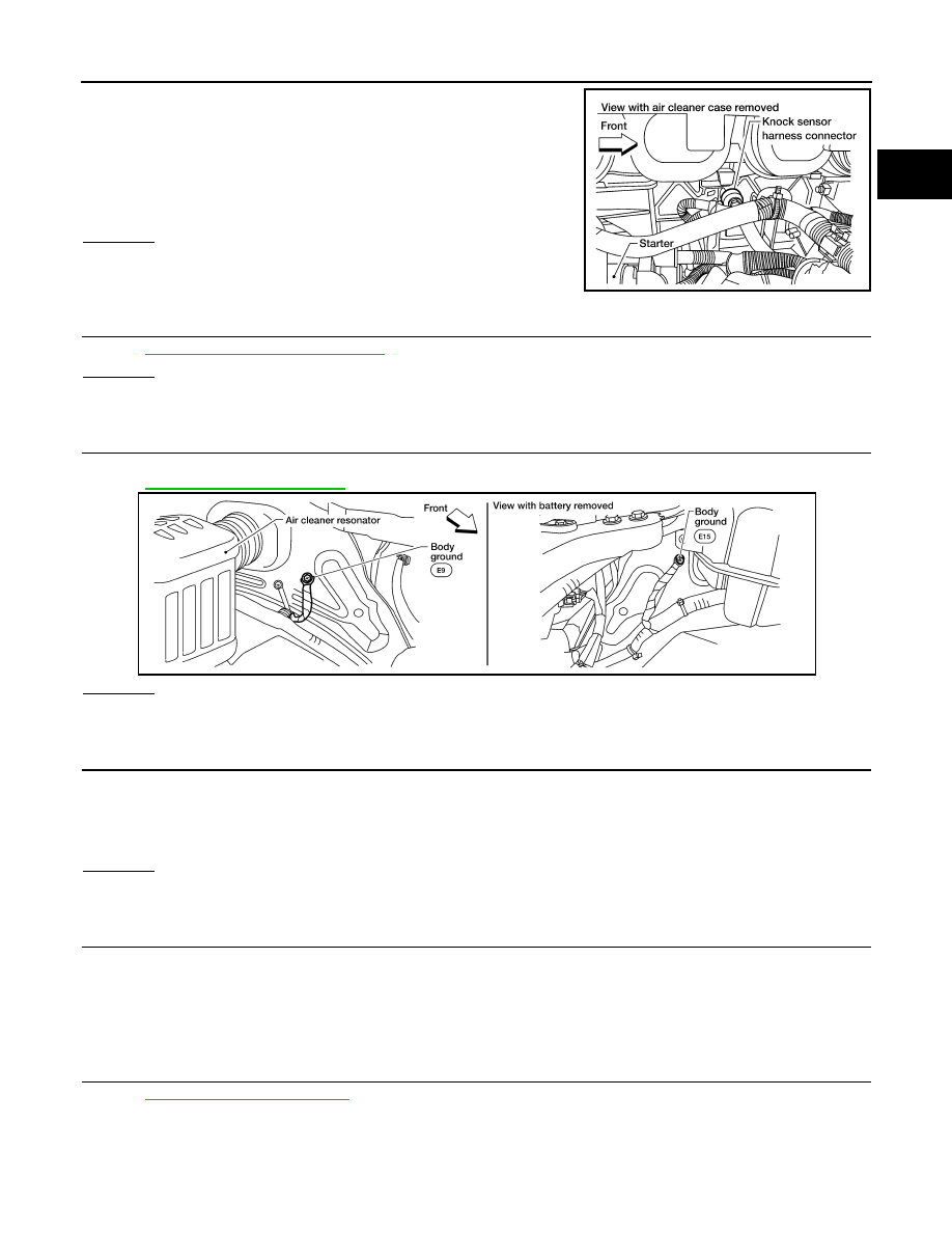
CHECK GROUND CONNECTIONS
Loosen and retighten two ground screws on the body.
Refer to
.
OK or NG
OK
>> GO TO 5.
NG
>> Repair or replace ground connections.
5.
CHECK KNOCK SENSOR SHIELD CIRCUIT FOR OPEN AND SHORT
1.
Disconnect knock sensor harness connector.
2.
Check harness continuity between knock sensor terminal 2 and ground. Refer to Wiring Diagram.
OK or NG
OK
>> GO TO 6.
NG
>> GO TO 7.
6.
DETECT MALFUNCTIONING PART
Check the following.
• Harness connectors F14, E5
• Harness for open or short between knock sensor and ground
>> Repair open circuit or short power in harness or connectors.
7.
CHECK INTERMITTENT INCIDENT
GI-46, "Intermittent Incident"
.
>> INSPECTION END
Continuity should exist.
BBIA0618E
BBIA0614E
Continuity should exist.