Nissan Frontier D40. Manual - part 352


  Index      Nissan     Nissan Frontier D40 (2010 year) - Service and Repair Manual


Search            


Content   ..  350  351  352  353   ..


Nissan Frontier D40. Manual - part 352


P0031, P0032 A/F SENSOR 1 HEATER

EC-99

< COMPONENT DIAGNOSIS >

[QR25DE]

C

D

E

F

G

H

I

J

K

L

M

A

EC

N

P

O

OK

>> GO TO 7.

NG

>> Repair or replace.

7.

REPLACE AIR FUEL RATIO (A/F) SENSOR 1

Replace air fuel ratio (A/F) sensor 1.

CAUTION:

• Discard any air fuel ratio (A/F) sensor which has been dropped from a height of more than 0.5 m

(19.7 in) onto a hard surface such as a concrete floor; use a new one.

• Before installing new air fuel ratio (A/F) sensor, clean exhaust system threads using Heated Oxygen

Sensor Thread Cleaner [commercial service tool (J-43897-18 or J-43897-12)] and approved anti-seize
lubricant (commercial service tool).

>> INSPECTION END

Component Inspection

INFOID:0000000005273070

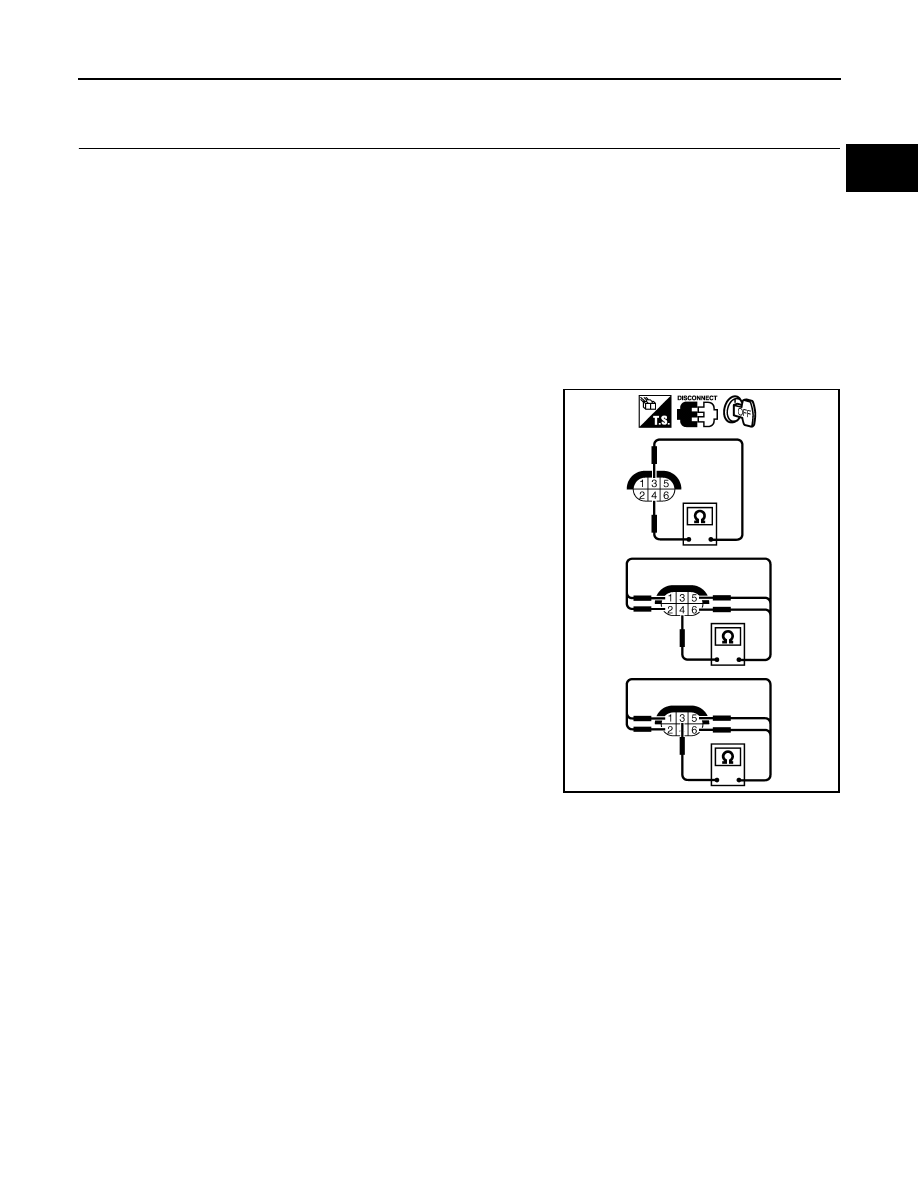
AIR FUEL RATIO (A/F) SENSOR 1 HEATER

Check resistance between terminals 3 and 4.

Check continuity between terminals 3 and 1, 2, 5, 6, terminals 4 and
1, 2, 5, 6.

If NG, replace the A/F sensor 1.

CAUTION:

• Discard any A/F sensor which has been dropped from a

height of more than 0.5 m (19.7 in) onto a hard surface such
as a concrete floor; use a new one.

• Before installing new A/F sensor, clean exhaust system

threads using Heated Oxygen Sensor Thread Cleaner [com-
mercial service tool (J-43897-18 or J-43897-12)] and approved
anti-seize lubricant (commercial service tool).

Resistance: 2.3 - 4.3

 [at 25

°

C (77

°

F)]

Continuity should not exist.

PBIB1684E

EC-100

< COMPONENT DIAGNOSIS >

[QR25DE]

P0037, P0038 HO2S2 HEATER

P0037, P0038 HO2S2 HEATER

Description

INFOID:0000000005273071

SYSTEM DESCRIPTION

The ECM performs ON/OFF control of the heated oxygen sensor 2 heater corresponding to the engine speed,
amount of intake air and engine coolant temperature.

OPERATION

On Board Diagnosis Logic

INFOID:0000000005273072

DTC Confirmation Procedure

INFOID:0000000005273073

NOTE:
If DTC Confirmation Procedure has been previously conducted, always turn ignition switch OFF and
wait at least 10 seconds before conducting the next test.
TESTING CONDITION:
Before performing the following procedure, confirm that battery voltage is between 10.5V and 16V at
idle.

 WITH CONSULT-III

1.

Start engine and warm it up to the normal operating temperature.

2.

Turn ignition switch OFF and wait at least 10 seconds.

3.

Start engine and keep the engine speed between 3,500 and 4,000 rpm for at least 1 minute under no load.

4.

Let engine idle for 1 minute.

5.

Check 1st trip DTC.

6.

If 1st trip DTC is detected, go to 

EC-101, "Diagnosis Procedure"

.

 WITH GST

Follow the procedure “WITH CONSULT-III” above.

Sensor

Input Signal to ECM

ECM Function

Actuator

Camshaft position sensor (PHASE)

Engine speed

Heated oxygen sensor 2 
heater control

Heated oxygen sensor 2 heater

Crankshaft position sensor (POS)

Engine coolant temperature sensor

Engine coolant temperature

Mass air flow sensor

Amount of intake air

Engine speed 

Heated oxygen sensor 2 heater

Above 3,600 rpm

OFF

Below 3,600 rpm after the following conditions are met.
• Engine: After warming up
• Keeping the engine speed between 3,500 and 4,000 rpm for 1 

minute and at idle for 1 minute under no load

ON

DTC No.

Trouble diagnosis name

DTC detecting condition

Possible cause

P0037
0037

Heated oxygen sensor 2 
heater control circuit low

The current amperage in the heated oxygen sensor 
2 heater circuit is out of the normal range.
(An excessively low voltage signal is sent to ECM 
through the heated oxygen sensor 2 heater.)

• Harness or connectors

(The heated oxygen sensor 2 heater 
circuit is open or shorted.)

• Heated oxygen sensor 2 heater

P0038
0038

Heated oxygen sensor 2 
heater control circuit high

The current amperage in the heated oxygen sensor 
2 heater circuit is out of the normal range.
(An excessively high voltage signal is sent to ECM 
through the heated oxygen sensor 2 heater.)

• Harness or connectors

(The heated oxygen sensor 2 heater 
circuit is shorted.)

• Heated oxygen sensor 2 heater

P0037, P0038 HO2S2 HEATER

EC-101

< COMPONENT DIAGNOSIS >

[QR25DE]

C

D

E

F

G

H

I

J

K

L

M

A

EC

N

P

O

Diagnosis Procedure

INFOID:0000000005273074

1.

CHECK GROUND CONNECTIONS

1.

Turn ignition switch OFF.

2.

Loosen and retighten two ground screws on the body. Refer to 

EC-90, "Ground Inspection"

.

OK or NG

OK

>> GO TO 2.

NG

>> Repair or replace ground connections.

2.

CHECK HO2S2 POWER SUPPLY CIRCUIT

1.

Disconnect heated oxygen sensor 2 harness connector.

2.

Turn ignition switch ON.

3.

Check voltage between HO2S2 terminal 3 and ground with
CONSULT-III or tester.

OK or NG

OK

>> GO TO 4.

NG

>> GO TO 3.

3.

DETECT MALFUNCTIONING PART

Check the following.
• Harness connectors E2, F32
• IPDM E/R connector E119
• 15A fuse (No.54)
• Harness for open or short between heated oxygen sensor 2 and fuse

>> Repair open circuit, short to ground or short to power in harness or connectors.

4.

CHECK HO2S2 OUTPUT SIGNAL CIRCUIT FOR OPEN AND SHORT

1.

Turn ignition switch OFF.

2.

Disconnect ECM harness connector.

3.

Check harness continuity between ECM terminal 25 and HO2S2 terminal 2.
Refer to Wiring Diagram.

BBIA0614E

BBIA0613E

Voltage: Battery voltage

PBIB0112E

EC-102

< COMPONENT DIAGNOSIS >

[QR25DE]

P0037, P0038 HO2S2 HEATER

4.

Also check harness for short to ground and short to power.

OK or NG

OK

>> GO TO 5.

NG

>> Repair open circuit, short to ground or short to power in harness or connectors.

5.

CHECK HEATED OXYGEN SENSOR 2 HEATER

Refer to 

EC-102, "Component Inspection"

.

OK or NG

OK

>> GO TO 6.

NG

>> Replace heated oxygen sensor 2.

6.

CHECK INTERMITTENT INCIDENT

Refer to 

GI-46, "Intermittent Incident"

.

>> INSPECTION END

Component Inspection

INFOID:0000000005273075

HEATED OXYGEN SENSOR 2 HEATER

1.

Check resistance between HO2S2 terminals as follows.

2.

If NG, replace heated oxygen sensor 2.

CAUTION:

• Discard any heated oxygen sensor which has been dropped

from a height of more than 0.5 m (19.7 in) onto a hard surface
such as a concrete floor; use a new one.

• Before installing new oxygen sensor, clean exhaust system

threads using Oxygen Sensor Thread Cleaner [commercial
service tool (J-43897-18 or J-43897-12)] and approved anti-
seize lubricant (commercial service tool).

Continuity should exist.

Terminal No.

Resistance

2 and 3

9.9 - 13.3 

 [at 25

°

C (77

°

F)]

1 and 2, 3, 4


(Continuity should not exist)

4 and 1, 2, 3

SEF249Y


Content   ..  350  351  352  353   ..