Nissan Frontier D40. Manual - part 351


  Index      Nissan     Nissan Frontier D40 (2010 year) - Service and Repair Manual


Search            


Content   ..  349  350  351  352   ..


Nissan Frontier D40. Manual - part 351


P0011 IVT CONTROL

EC-95

< COMPONENT DIAGNOSIS >

[QR25DE]

C

D

E

F

G

H

I

J

K

L

M

A

EC

N

P

O

7.

Check 1st trip DTC.

8.

If the 1st trip DTC is detected, go to 

EC-95, "Diagnosis Procedure"

.

 WITH GST

Follow the procedure “WITH CONSULT-III” above.

Diagnosis Procedure

INFOID:0000000005273064

1.

CHECK OIL PRESSURE WARNING LAMP

1.

Start engine.

2.

Check oil pressure warning lamp and confirm it is not illumi-
nated.

OK or NG

OK

>> GO TO 2.

NG

>> Go to 

LU-9, "Inspection"

.

2.

CHECK INTAKE VALVE TIMING CONTROL SOLENOID VALVE

Refer to 

EC-96, "Component Inspection"

.

OK or NG

OK

>> GO TO 3.

NG

>> Replace intake valve timing control solenoid valve.

3.

CHECK CRANKSHAFT POSITION SENSOR (POS)

Refer to 

EC-199, "Component Inspection"

.

OK or NG

OK

>> GO TO 4.

NG

>> Replace crankshaft position sensor (POS).

4.

CHECK CAMSHAFT POSITION SENSOR (PHASE)

Refer to 

EC-204, "Component Inspection"

.

OK or NG

OK

>> GO TO 5.

NG

>> Replace camshaft position sensor (PHASE).
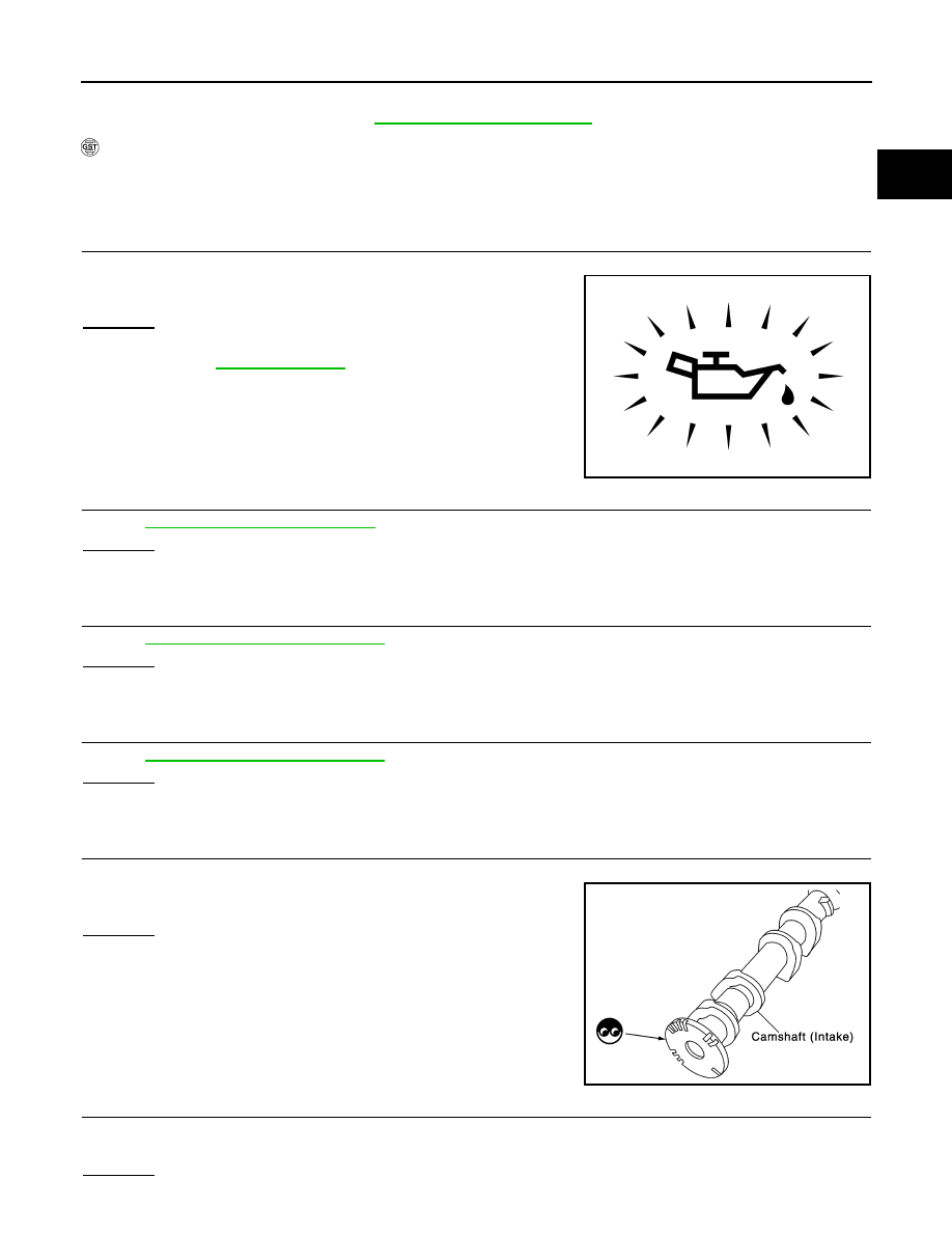
5.

CHECK CAMSHAFT (INTAKE)

Check the following.
• Accumulation of debris on the signal plate of camshaft rear end
• Chipping signal plate of camshaft rear end

OK or NG

OK

>> GO TO 6.

NG

>> Remove debris and clean the signal plate of camshaft

rear end or replace camshaft.

6.

CHECK TIMING CHAIN INSTALLATION

Check service records for any recent repairs that may cause timing chain misaligned.
Are there any service records that may cause timing chain misaligned?

Yes or No

PBIA8559J

PBIB0565E

EC-96

< COMPONENT DIAGNOSIS >

[QR25DE]

P0011 IVT CONTROL

Yes

>> Check timing chain installation. Refer to 

EM-44, "Removal and Installation"

.

No

>> GO TO 7.

7.

CHECK LUBRICATION CIRCUIT

Refer to 

EM-52, "Removal and Installation"

.

OK or NG

OK

>> GO TO 8.

NG

>> Clean lubrication line.

8.

CHECK INTERMITTENT INCIDENT

Refer to

GI-46, "Intermittent Incident"

.

>> INSPECTION END

Component Inspection

INFOID:0000000005273065

INTAKE VALVE TIMING CONTROL SOLENOID VALVE

1.

Disconnect intake valve timing control solenoid valve harness connector.

2.

Check resistance between intake valve timing control solenoid
valve as follows.

If NG, replace intake valve timing control solenoid valve.
If OK, go to next step.

3.

Remove intake valve timing control solenoid valve.

4.

Provide 12V DC between intake valve timing control solenoid
valve terminals and then interrupt it. Make sure that the plunger
moves as shown in the figure.

CAUTION:

Never apply 12V DC continuously for 5 seconds or more.
Doing so may result in damage to the coil in intake valve
timing control solenoid valve.
If NG, replace intake valve timing control solenoid valve.
NOTE:
Always replace O-ring when intake valve timing control
solenoid valve is removed.

Terminal

Resistance

1 and 2

7.0 - 7.7

 [at 20

°

C (68

°

F)]

1 or 2 and ground

∞Ω

(Continuity should not exist.)

PBIB0193E

PBIB2275E

P0031, P0032 A/F SENSOR 1 HEATER

EC-97

< COMPONENT DIAGNOSIS >

[QR25DE]

C

D

E

F

G

H

I

J

K

L

M

A

EC

N

P

O

P0031, P0032 A/F SENSOR 1 HEATER

Description

INFOID:0000000005273066

SYSTEM DESCRIPTION

The ECM performs ON/OFF duty control of the A/F sensor 1 heater corresponding to the engine operating
condition to keep the temperature of A/F sensor 1 element at the specified range.

On Board Diagnosis Logic

INFOID:0000000005273067

DTC Confirmation Procedure

INFOID:0000000005273068

NOTE:
If DTC Confirmation Procedure has been previously conducted, always turn ignition switch OFF and
wait at least 10 seconds before conducting the next test.
TESTING CONDITION:
Before performing the following procedure, confirm that battery voltage is between 10.5V and 16V at
idle.

 WITH CONSULT-III

1.

Start engine and run it for at least 10 seconds at idle speed.

2.

Check 1st trip DTC.

3.

If 1st trip DTC is detected, go to 

EC-97, "Diagnosis Procedure"

.

 WITH GST

Follow the procedure “WITH CONSULT-III” above.

Diagnosis Procedure

INFOID:0000000005273069

1.

CHECK GROUND CONNECTIONS

1.

Turn ignition switch OFF.

2.

Loosen and retighten two ground screws on the body. Refer to 

EC-90, "Ground Inspection"

.

OK or NG

Sensor

Input Signal to ECM

ECM function

Actuator

Camshaft position sensor (PHASE)
Crankshaft position sensor (POS)

Engine speed

Air fuel ratio (A/F) sensor 
1 heater control

Air fuel ratio (A/F) sensor 1 
heater

Mass air flow sensor

Amount of intake air

DTC No.

Trouble diagnosis name

DTC detecting condition

Possible cause

P0031
0031

Air fuel ratio (A/F) sensor 
1 heater control circuit 
low

The current amperage in the air fuel ratio (A/F) 
sensor 1 heater circuit is out of the normal range.
(An excessively low voltage signal is sent to ECM 
through the air fuel ratio (A/F) sensor 1 heater.)

• Harness or connectors

(The A/F sensor 1 heater circuit is 
open or shorted.)

• Air fuel ratio (A/F) sensor 1 heater

P0032
0032

Air fuel ratio (A/F) sensor 
1 heater control circuit 
high

The current amperage in the air fuel ratio (A/F) 
sensor 1 heater circuit is out of the normal range.
(An excessively high voltage signal is sent to ECM 
through the air fuel ratio (A/F) sensor 1 heater.)

• Harness or connectors

(The A/F sensor 1 heater circuit is 
shorted.)

• Air fuel ratio (A/F) sensor 1 heater

BBIA0614E

EC-98

< COMPONENT DIAGNOSIS >

[QR25DE]

P0031, P0032 A/F SENSOR 1 HEATER

OK

>> GO TO 2.

NG

>> Repair or replace ground connections.

2.

CHECK AIR FUEL RATIO (A/F) SENSOR 1 POWER SUPPLY CIRCUIT

1.

Disconnect air fuel ratio (A/F) sensor 1 harness connector.

2.

Turn ignition switch ON.

3.

Check voltage between A/F sensor 1 terminal 3 and ground with
CONSULT-III or tester.

OK or NG

OK

>> GO TO 4.

NG

>> GO TO 3.

3.

DETECT MALFUNCTIONING PART

Check the following.
• Harness connectors E2, F32
• IPDM E/R harness connector E119
• 15A fuse (No.54)
• Harness for open or short between A/F sensor 1 and fuse

>> Repair or replace harness or connectors.

4.

CHECK A/F SENSOR 1 HEATER OUTPUT SIGNAL CIRCUIT

1.

Turn ignition switch OFF.

2.

Disconnect ECM harness connector.

3.

Check harness continuity between ECM terminal 2 and A/F sensor 1 terminal 4. 
Refer to Wiring Diagram.

4.

Also check harness for short to ground and short to power.

OK or NG

OK

>> GO TO 5.

NG

>> Repair open circuit, short to ground or short to power in harness or connectors.

5.

CHECK A/F SENSOR 1 HEATER

Refer to 

EC-99, "Component Inspection"

.

OK or NG

OK

>> GO TO 6.

NG

>> GO TO 7.

6.

CHECK INTERMITTENT INCIDENT

Perform 

GI-42, "Work Flow"

.

OK or NG

BBIA0617E

Voltage: Battery voltage

PBIB1683E

Continuity should exist.


Content   ..  349  350  351  352   ..