Nissan Frontier D40. Manual - part 197
WATER PUMP
CO-49
< ON-VEHICLE REPAIR >
[VQ40DE]
C
D
E
F
G
H
I
J
K
L
M
A
CO
N
P
O
WATER PUMP
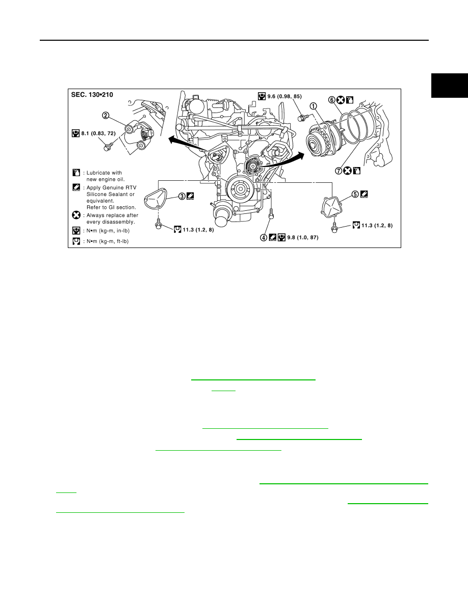
Exploded View
INFOID:0000000005276116
Removal and Installation
INFOID:0000000005276117
CAUTION:
• When removing water pump assembly, be careful not to get engine coolant on timing chain and drive
belt.
• Water pump cannot be disassembled and should be replaced as a unit.
• After installing water pump, connect hose and clamp securely, then check for leaks.
REMOVAL
1.
Remove engine under cover. Refer to
EXT-13, "Removal and Installation"
.
2.
Drain engine coolant from radiator. Refer to
CAUTION:
• Perform this step when engine is cold.
• Do not spill engine coolant on timing chain and drive belt.
3.
Remove the engine room cover. Refer to
EM-138, "Removal and Installation"
4.
Remove air duct and resonator assembly. Refer to
EM-139, "Removal and Installation"
.
5.
Remove drive belt. Refer to
EM-127, "Removal and Installation"
6.
Remove radiator hose (upper).
7.
Remove coolant reservoir hose from the radiator.
8.
Remove engine cooling fan (Motor driven type). Refer to
CO-47, "Removal and Installation (Motor driven
.
9.
Remove engine cooling fan (Crankshaft driven type) and fan bracket. Refer to
Installation (Crankshaft driven type)"
1.
Water pump
2.
Timing chain tensioner (primary)
3.
Chain tensioner cover
4.
Water drain plug (front)
5.
Water pump cover
6.
O-ring
7.
O-ring
PBIC2833E