Nissan Frontier D40. Manual - part 195


  Index      Nissan     Nissan Frontier D40 (2010 year) - Service and Repair Manual


Search            


Content   ..  193  194  195  196   ..


Nissan Frontier D40. Manual - part 195


ENGINE COOLANT

CO-41

< ON-VEHICLE MAINTENANCE >

[VQ40DE]

C

D

E

F

G

H

I

J

K

L

M

A

CO

N

P

O

1.

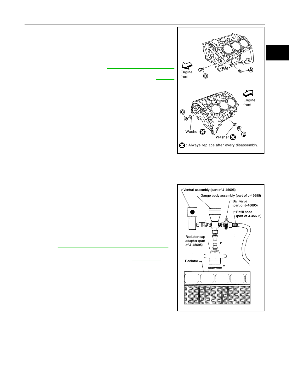
Close the radiator drain plug. Install the reservoir tank, cylinder
block drain plugs (A), (B), (C), (D) and block heater if equipped,
if removed for a total system drain or for engine removal or
repair.
• The radiator must be completely empty of coolant and water.
• Apply sealant to the threads of the cylinder block drain plugs

(A), (B), (C), (D). Use Genuine High Performance Thread
Sealant or equivalent. Refer to 

GI-22, "Recommended Chemi-

cal Products and Sealants"

.

• Tighten each plug to the specified torque. Refer to 

EM-215,

"Disassembly and Assembly"

.

2.

Set the vehicle heater controls to the full HOT and heater ON position. Turn the vehicle ignition ON with
the engine OFF as necessary to activate the heater mode.

3.

Remove the vented reservoir cap and replace it with a non-vented reservoir cap before filling the cooling
system.

4.

Install the Tool by installing the radiator cap adapter onto the
radiator neck opening. Then attach the gauge body assembly
with the refill tube and the venturi assembly to the radiator cap
adapter.

5.

Insert the refill hose into the coolant mixture container that is
placed at floor level. Make sure the ball valve is in the closed
position. 
• Use recommended coolant or equivalent.

Refer to 

MA-16, "For North America: Fluids and Lubricants"

.

6.

Install an air hose to the venturi assembly, the air pressure must
be within specification. 

CAUTION:

The compressed air supply must be equipped with an air dryer.

7.

The vacuum gauge will begin to rise and there will be an audible hissing noise. During this process open
the ball valve on the refill hose slightly. Coolant will be visible rising in the refill hose. Once the refill hose is
full of coolant, close the ball valve. This will purge any air trapped in the refill hose.

WLIA0020E

Tool number

: KV991J0070 (J-45695)

Cooling system capacity 
(with reservoir)

: Refer to 

MA-16, "For 

North America: Fluids and 
Lubricants"

.

Compressed air 
supply pressure

: 549 - 824 kPa (5.6 - 8.4 kg/cm

2

80 - 119 psi)

LLIA0058E

CO-42

< ON-VEHICLE MAINTENANCE >

[VQ40DE]

ENGINE COOLANT

8.

Continue to draw the vacuum until the gauge reaches 28 inches
of vacuum. The gauge may not reach 28 inches in high altitude
locations, use the vacuum specifications based on the altitude
above sea level.

9.

When the vacuum gauge has reached the specified amount, disconnect the air hose and wait 20 seconds
to see if the system loses any vacuum. If the vacuum level drops, perform any necessary repairs to the
system and repeat steps 6 - 8 to bring the vacuum to the specified amount. Recheck for any leaks. 

10. Place the coolant container (with the refill hose inserted) at the same level as the top of the radiator. Then

open the ball valve on the refill hose so the coolant will be drawn up to fill the cooling system. The cooling
system is full when the vacuum gauge reads zero.

CAUTION:

Do not allow the coolant container to get too low when filling, to avoid air from being drawn into
the cooling system. 

11. Remove the Tool from the radiator neck opening and install the radiator cap.
12. Remove the non-vented reservoir cap.

13. Fill the cooling system reservoir tank to the specified level. Run the engine to warm up the cooling system

and top up the system as necessary before installing the vented reservoir cap.

FLUSHING COOLING SYSTEM

1.

Drain the water from the engine cooling system. Refer to 

CO-39, "Changing Engine Coolant"

.

2.

Fill the radiator and the reservoir tank (to the “MAX” line), with water. Reinstall the radiator cap and leave
the vented reservoir cap off.

3.

Run the engine until it reaches normal operating temperature.

4.

Press the engine accelerator two or three times under no-load.

5.

Stop the engine and wait until it cools down.

6.

Drain the water from the engine cooling system. Refer to 

CO-39, "Changing Engine Coolant"

.

7.

Repeat steps 2 through 6 until clear water begins to drain from the radiator.

Altitude above sea level

Vacuum gauge reading

0 - 100 m (328 ft)

: 28 inches of vacuum

300 m (984 ft)

: 27 inches of vacuum

500 m (1,641 ft)

: 26 inches of vacuum

1,000 m (3,281 ft)

: 24 - 25 inches of vacuum

LLIA0057E

RADIATOR

CO-43

< ON-VEHICLE REPAIR >

[VQ40DE]

C

D

E

F

G

H

I

J

K

L

M

A

CO

N

P

O

ON-VEHICLE REPAIR

RADIATOR

Exploded View

INFOID:0000000005276110

Removal and Installation

INFOID:0000000005276111

WARNING:

Do not remove radiator cap when engine is hot. Serious burns could occur from high-pressure engine
coolant escaping from radiator. Wrap a thick cloth around the cap. Slowly turn it a quarter of a turn to
release built-up pressure. Carefully remove radiator cap by turning it all the way.

REMOVAL

1.

Remove engine under cover. Refer to 

EXT-13, "Removal and Installation"

.

2.

Drain engine coolant from radiator. Refer to 

CO-38

.

CAUTION:

• Perform this step when engine is cold.

1.

Radiator mounting bracket

2.

Mounting rubber (upper)

3.

Radiator cap

4.

Radiator

5.

Mounting rubber (lower)

6.

A/T fluid cooler hose

7.

A/T fluid cooler hose (if equipped)

8.

O-ring

9.

Drain plug

10. Cooling fan assembly (Motor driven 

type)

11.

Radiator shroud (upper)

12. Radiator hose (lower)

13. Radiator shroud (lower)

14. Reservoir tank hose

15. Reservoir tank cap

16. Reservoir tank

17. Water hose

18. Radiator hose (upper)

A.

To heater return tube

B.

To water pipe

C.

To A/T cooler tube

D.

To water inlet and thermostat assembly

Vehicle front

PBIC3861E

CO-44

< ON-VEHICLE REPAIR >

[VQ40DE]

RADIATOR

• Do not spill engine coolant on drive belts.

3.

Remove engine room cover. Refer to 

EM-138, "Removal and Installation"

.

4.

Remove air duct and resonator assembly and air cleaner case (upper). Refer to 

EM-139, "Removal and

Installation"

.

5.

Remove reservoir tank hose.

6.

Remove radiator hoses (upper and lower).

CAUTION:

Be careful not to allow engine coolant to contact drive belts.

7.

Disconnect A/T fluid cooler hoses, if equipped.
• Install blind plug to avoid leakage of A/T fluid.

8.

Remove radiator shroud (lower).

9.

Remove radiator shroud (upper).

10. Remove engine cooling fan (Motor driven type). Refer to 

CO-47, "Removal and Installation (Motor driven

type)"

.

11. Remove front grille. Refer to 

EXT-18, "Removal and Installation"

.

12. Remove the upper radiator mounting bracket bolts.

13. Remove the two A/C condenser bolts.

14. Remove radiator as follows:

CAUTION:

Do not damage or scratch A/C condenser and radiator core when removing.

a.

With lifting and pulling radiator in a rear direction, disassemble
mounting rubber (lower) from radiator core support center.

CAUTION:

Because A/C condenser is attached to the front-lower por-
tion of radiator, moving it in the rear direction should be at a
minimum.

LBIA0419E

LBIA0421E

PBIC1936E


Content   ..  193  194  195  196   ..