Nissan Frontier D40. Manual - part 150


  Index      Nissan     Nissan Frontier D40 (2010 year) - Service and Repair Manual


Search            


Content   ..  148  149  150  151   ..


Nissan Frontier D40. Manual - part 150


BRC-298

< REMOVAL AND INSTALLATION >

[TYPE 3]

WHEEL SENSOR

REMOVAL AND INSTALLATION

WHEEL SENSOR

Removal and Installation

INFOID:0000000005593799

REMOVAL

1.

Remove wheel sensor bolt.
• When removing the front wheel sensor, first remove the disc rotor to gain access to the front wheel sen-

sor. Refer to 

BR-41, "Removal and Installation of Brake Caliper and Disc Rotor"

.

2.

Pull the wheel sensor straight out, being careful to turn it as little as possible.

CAUTION:

• Be careful not to damage the wheel sensor edge and sensor rotor teeth.
• Do not pull on the wheel sensor harness.

3.

Disconnect wheel sensor harness connector, then remove the wheel sensor harness from the mounts to
remove the wheel sensor.

INSTALLATION

Installation is in the reverse order of removal.
• Before installing wheel sensors do the following:
- Inspect and replace the wheel sensor if damaged.
- Clean the wheel sensor hole and mating surface with brake cleaner and a lint-free cloth. Be careful that dirt

and debris do not enter the hub and bearing assembly or the rear axle.
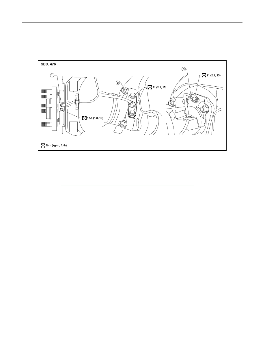
1.

Front wheel sensor

2.

Rear wheel sensor (C200)

3.

Rear wheel sensor (M226)

WFIA0339E

SENSOR ROTOR

BRC-299

< REMOVAL AND INSTALLATION >

[TYPE 3]

C

D

E

G

H

I

J

K

L

M

A

B

BRC

N

O

P

SENSOR ROTOR

Removal and Installation

INFOID:0000000005593800

FRONT

Removal and Installation

The wheel sensor rotors are built into the wheel hubs and are not removable. If damaged, replace wheel hub
and bearing assembly. Refer to 

FAX-8, "Removal and Installation"

REAR (C200)

Removal and Installation

It is necessary to disassemble the rear axle to replace the sensor rotor. Perform the axle shaft assembly
removal procedure to replace sensor rotor. Refer to 

RAX-7, "Removal and Installation"

.

REAR (M226)

Removal

1.

Remove the axle shaft assembly. Refer to 

RAX-19, "Removal and Installation"

.

2.

Pull the sensor rotor off of the axle shaft using Tool and a suitable press.

Installation

1.

Install the new sensor rotor on the axle shaft using a suitable
length steel tube and a press. Make sure the sensor rotor is fully
seated.

CAUTION:

Do not reuse the old sensor rotor.

2.

Install the axle shaft assembly. Refer to 

RAX-19, "Removal and

Installation"

.

CAUTION:

Do not reuse the axle oil seal. The axle oil seal must be
replaced every time the axle shaft assembly is removed
from the axle shaft housing.

Tool number

: ST30031000 (

)

WFIA0341E

BRC-300

< REMOVAL AND INSTALLATION >

[TYPE 3]

ACTUATOR AND ELECTRIC UNIT (ASSEMBLY)

ACTUATOR AND ELECTRIC UNIT (ASSEMBLY)

Removal and Installation

INFOID:0000000005275391

Type 3

REMOVAL

1.

Disconnect the negative battery terminal.

2.

Drain the brake fluid. Refer to 

BR-21, "Drain and Refill"

.

3.

Remove air cleaner case. Refer to 

EM-139, "Exploded View"

.

4.

Disconnect the actuator harness from the ABS actuator and electric unit (control unit).

CAUTION:

• To remove the brake tubes, use a flare nut wrench to prevent the flare nuts and brake tubes from

being damaged.

• Be careful not to splash brake fluid on painted areas.

5.

Disconnect the brake tubes.

6.

Remove the three bolts and remove the ABS actuator and electric unit (control unit).

INSTALLATION

Installation is in the reverse order of removal.
• If the ABS actuator and electric unit (control unit) is replaced, make sure to adjust position of steering angle

sensor. Refer to 

BRC-189, "ADJUSTMENT OF STEERING ANGLE SENSOR NEUTRAL POSITION : Spe-

cial Repair Requirement"

.

ALFIA0146ZZ

1.

From master cylinder secondary side
18.2 N·m (1.9 kg-m, 13 ft-lb)

2.

To rear right disc brake
13.0 N·m (1.3 kg-m, 10 ft-lb)

3.

To rear left disc brake
13.0 N·m (1.3 kg-m, 10 ft-lb)

4.

To front right disc brake
13.0 N·m (1.3 kg-m, 10 ft-lb)

5.

To front left disc brake
13.0 N·m (1.3 kg-m, 10 ft-lb)

6.

From master cylinder primary side
18.2 N·m (1.9 kg-m, 13 ft-lb)

7.

ABS actuator and electric unit (control 
unit)

8.

Harness connector

Front

ACTUATOR AND ELECTRIC UNIT (ASSEMBLY)

BRC-301

< REMOVAL AND INSTALLATION >

[TYPE 3]

C

D

E

G

H

I

J

K

L

M

A

B

BRC

N

O

P

CAUTION:

• All hoses and piping (tubes) must be free from excessive bending, twisting and pulling.
• Make sure there is no interference with other parts when turning steering both clockwise and coun-

terclockwise.

• The brake piping is an important safety part. If a brake fluid leak is detected, always disassemble the

parts. Replace applicable part with a new one, if necessary.

• Be careful not to splash brake fluid on painted areas; it way cause paint damage. If brake fluid is

splashed on painted areas, wash it away with water immediately.

• Do not bend or twist brake hose sharply, or strongly pull it.
• When removing components, cover connections so that no dirt, dust, or other foreign matter gets in.
• Do not reuse drained brake fluid.
• After installation of the ABS actuator and electric unit (control unit), refill brake system with new

brake fluid. Then bleed the air from the system. Refer to 

BR-21, "Bleeding Brake System"

.


Content   ..  148  149  150  151   ..