Nissan Frontier D40. Manual - part 138


  Index      Nissan     Nissan Frontier D40 (2010 year) - Service and Repair Manual


Search            


Content   ..  136  137  138  139   ..


Nissan Frontier D40. Manual - part 138


BRC-250

< COMPONENT DIAGNOSIS >

[TYPE 3]

C1155 BRAKE FLUID LEVEL SWITCH

Is the inspection result normal?

YES

>> GO TO 3

NO

>> Repair or replace malfunctioning components.

3.

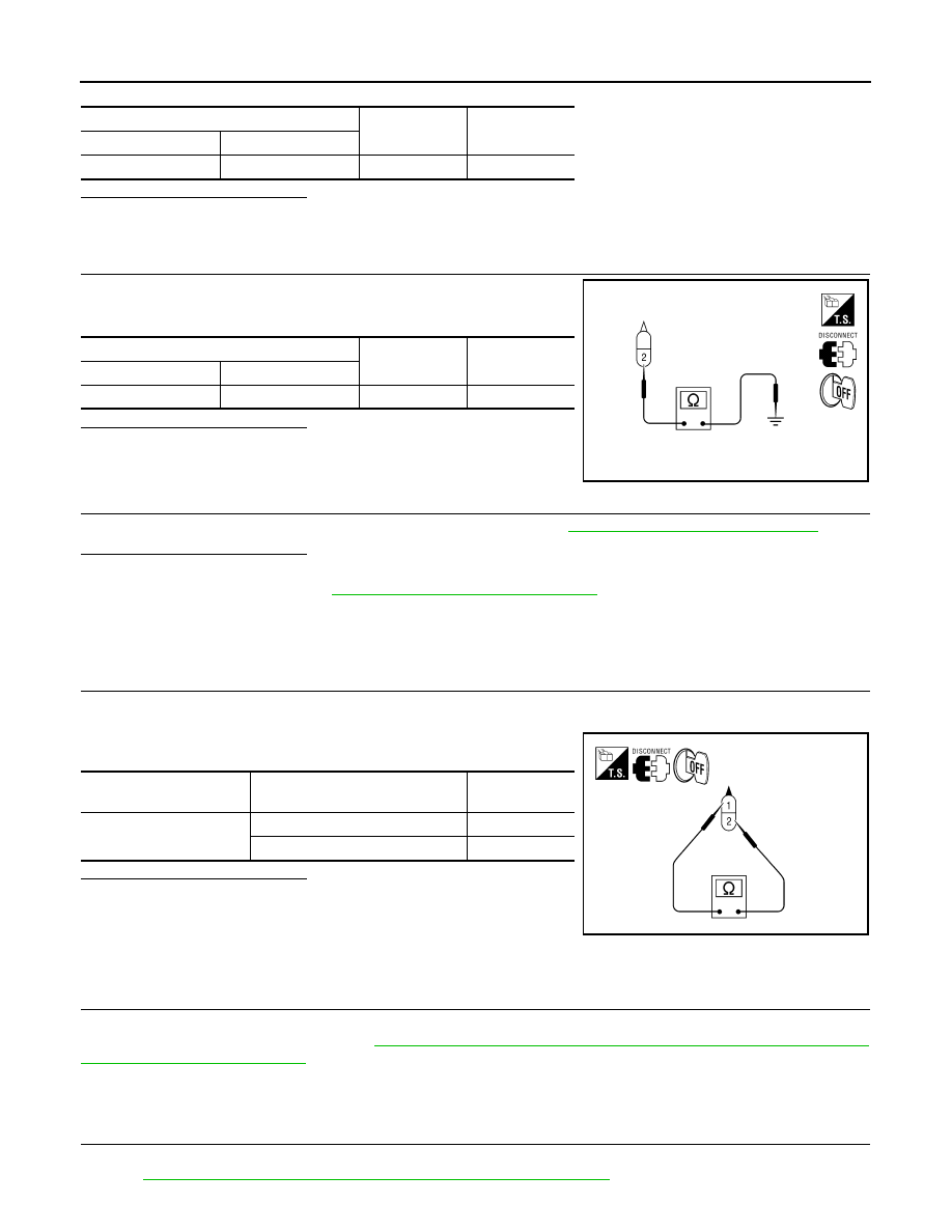
CHECK BRAKE FLUID LEVEL SWITCH GROUND

Check continuity between brake fluid level switch connector E21 ter-
minal 2 and ground.

Is the inspection result normal?

YES

>> GO TO 4

NO

>> Repair or replace malfunctioning components.

4.

CHECK BRAKE FLUID LEVEL SWITCH

Perform the brake fluid level switch component inspection. Refer to 

BRC-250, "Component Inspection"

.

Is the inspection result normal?

YES

>> Perform self-diagnosis again. If the same results appear, replace ABS actuator and electric unit

(control unit). Refer to 

BRC-300, "Removal and Installation"

.

NO

>> Replace brake fluid level switch.

Component Inspection

INFOID:0000000005275316

1.

CHECK BRAKE FLUID LEVEL SWITCH

1.

Turn ignition switch OFF.

2.

Disconnect brake fluid level switch connector.

3.

Check continuity between brake fluid level switch terminals.

Is the inspection result normal?

YES

>> Inspection End

NO

>> Replace brake fluid level switch.

Special Repair Requirement

INFOID:0000000005549807

1.

ADJUSTMENT OF STEERING ANGLE SENSOR NEUTRAL POSITION

Always perform neutral position adjustment for the steering angle sensor when replacing the ABS actuator
and electric unit (control unit). Refer to 

BRC-189, "ADJUSTMENT OF STEERING ANGLE SENSOR NEU-

TRAL POSITION : Description"

.

>> GO TO 2

2.

CALIBRATION OF DECEL G SENSOR

Always perform calibration of decel G sensor when replacing the ABS actuator and electric unit (control unit).
Refer to 

BRC-190, "CALIBRATION OF DECEL G SENSOR : Description"

.

ABS actuator and electric unit (control unit)

Continuity

Connector

Terminal

E127 (A)

28

Ground

No

Brake fluid level switch

Continuity

Connector

Terminal

E21

2

Ground

Yes

AWFIA0026ZZ

Brake fluid level

switch terminal

Condition

Continuity

 2

Brake fluid reservoir is full.

No

Brake fluid reservoir is empty.

Yes

ALFIA0026ZZ

C1155 BRAKE FLUID LEVEL SWITCH

BRC-251

< COMPONENT DIAGNOSIS >

[TYPE 3]

C

D

E

G

H

I

J

K

L

M

A

B

BRC

N

O

P

>> END

BRC-252

< COMPONENT DIAGNOSIS >

[TYPE 3]

C1156 ST ANG SEN COM CIR

C1156 ST ANG SEN COM CIR

Description

INFOID:0000000005275318

The steering angle sensor is connected to the ABS actuator and electric unit (control unit) in addition to CAN
lines. CAN (Controller Area Network) is a serial communication line for real time application. It is an on-vehicle
multiplex communication line with high data communication speed and excellent error detection ability. Many
electronic control units are equipped onto a vehicle, and each control unit shares information and links with
other control units during operation (not independent). In CAN communication, control units are connected
with 2 communication lines (CAN H line, CAN L line) allowing a high rate of information transmission with less
wiring. Each control unit transmits/receives data but selectively reads required data only.

DTC Logic

INFOID:0000000005275319

DTC DETECTION LOGIC

DTC CONFIRMATION PROCEDURE

1.

CHECK SELF-DIAGNOSIS RESULTS

Check the self-diagnosis results.

Is above displayed on the self-diagnosis display?

YES

>> Proceed to diagnosis procedure. Refer to 

BRC-252, "Diagnosis Procedure"

.

NO

>> Inspection End

Diagnosis Procedure

INFOID:0000000005275320

1.

CONNECTOR INSPECTION

1.

Turn ignition switch OFF.

2.

Disconnect ABS actuator and electric unit (control unit) connector.

3.

Check terminals for deformation, disconnection, looseness, and so on. If any malfunction is found, repair
or replace terminals.

4.

Reconnect connector and perform self-diagnosis. Refer to 

BRC-212, "CONSULT-III Function (ABS)"

.

Is above displayed on the self-diagnosis display?

YES

>> Refer to 

LAN-14, "Trouble Diagnosis Flow Chart"

.

NO

>> Inspection End

DTC

Display item

Malfunction detected condition

Possible cause

C1156

ST ANG SEN COM CIR

When steering angle sensor is not transmitting CAN 
communication signal to the ABS actuator and electric 
unit (control unit).

• Harness or connector
• CAN communication line
• Steering angle sensor
• ABS actuator and electric unit 

(control unit)

Self-diagnosis results

ST ANG SEN COM CIR

Self-diagnosis results

CAN COMM CIRCUIT

ST ANG SEN COM CIR

C1160 DECEL G SEN SET

BRC-253

< COMPONENT DIAGNOSIS >

[TYPE 3]

C

D

E

G

H

I

J

K

L

M

A

B

BRC

N

O

P

C1160 DECEL G SEN SET

Description

INFOID:0000000005275321

The yaw rate/side/decel G sensor detects the yaw rate/side/decel G affecting the vehicle, and transmits the
data to the ABS actuator and electric unit (control unit) as an analog voltage signal.

DTC Logic

INFOID:0000000005275322

DTC DETECTION LOGIC

DTC CONFIRMATION PROCEDURE

1.

CHECK SELF-DIAGNOSIS RESULTS

Check the self-diagnosis results.

Is above displayed on the self-diagnosis display?

YES

>> Proceed to diagnosis procedure. Refer to 

BRC-253, "Diagnosis Procedure"

.

NO

>> Inspection End

Diagnosis Procedure

INFOID:0000000005275323

1.

PERFORM SELF-DIAGNOSIS

Perform ABS actuator and electric unit (control unit) self-diagnosis. Refer to 

BRC-212, "CONSULT-III Function

(ABS)"

.

Do self-diagnosis results indicate anything other than shown above?

YES

>> Perform repair or replacement for the item indicated.

NO

>> Perform calibration of decel G sensor. Refer to 

BRC-190, "CALIBRATION OF DECEL G SENSOR

: Description"

. GO TO 2

2.

PERFORM SELF-DIAGNOSIS AGAIN

1.

Turn the ignition switch to OFF and then to ON and erase self-diagnosis results. Refer to 

BRC-212, "CON-

SULT-III Function (ABS)"

.

2.

Perform ABS actuator and electric unit (control unit) self-diagnosis again. Refer to 

BRC-212, "CONSULT-

III Function (ABS)"

.

Are any self-diagnosis results displayed?

YES

>> Replace yaw rate/side/decel G sensor. Refer to 

BRC-303, "Removal and Installation"

.

NO

>> Inspection End

DTC

Display item

Malfunction detected condition

Possible cause

C1160

DECEL G SEN SET

ABS decel G sensor adjustment is incomplete.

• Decel G sensor calibration
• Yaw rate/side/decel G sensor
• ABS actuator and electric unit 

(control unit)

Self-diagnosis results

DECEL G SEN SET

Self-diagnosis results

DECEL G SEN SET


Content   ..  136  137  138  139   ..