Nissan Frontier D40. Manual - part 1014


  Index      Nissan     Nissan Frontier D40 (2010 year) - Service and Repair Manual


Search            


Content   ..  1012  1013  1014  1015   ..


Nissan Frontier D40. Manual - part 1014


POWER STEERING OIL PUMP

ST-19

< REMOVAL AND INSTALLATION >

C

D

E

F

H

I

J

K

L

M

A

B

ST

N

O

P

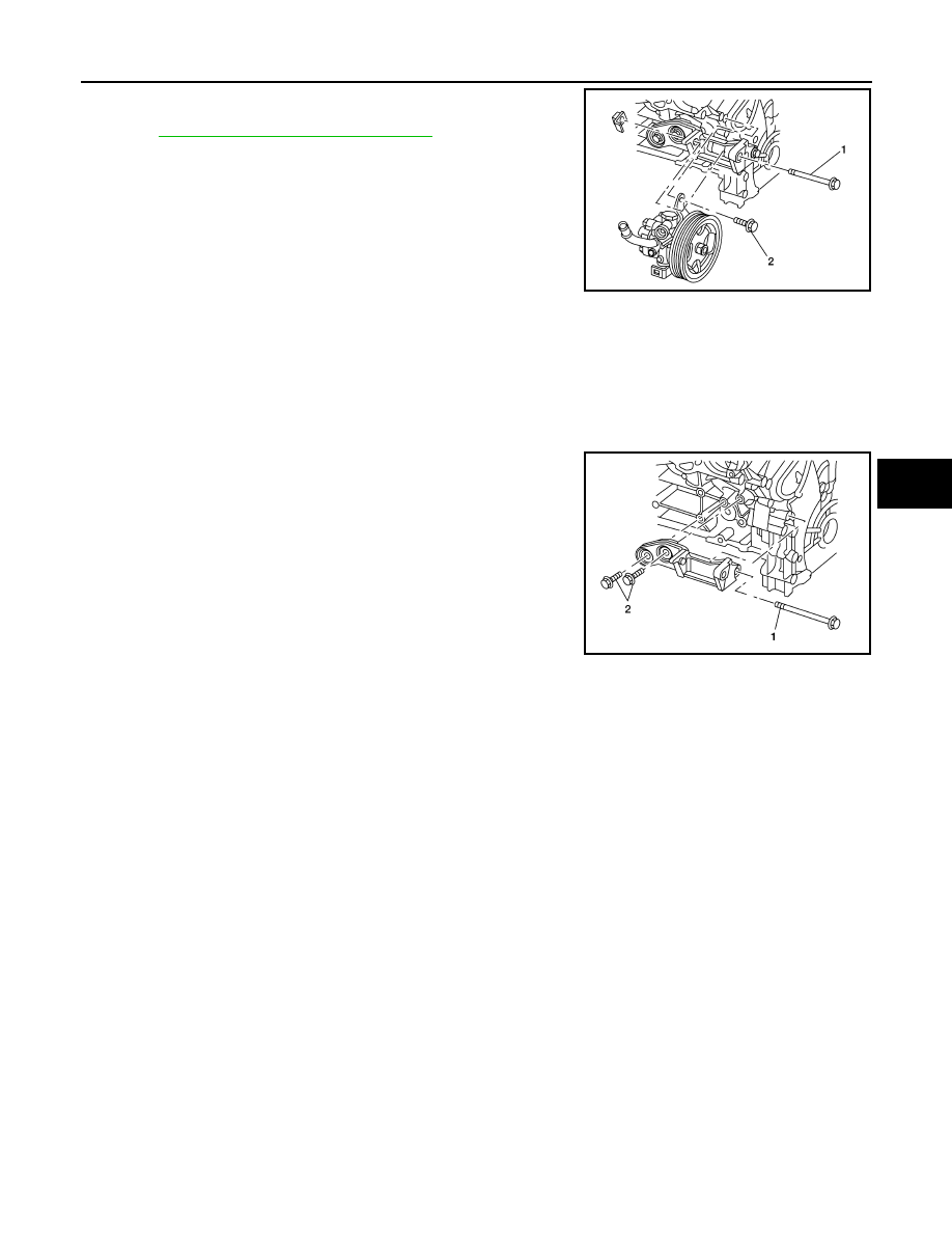
• On VQ40DE, install the bolts to specification in the order shown.
• After installation, bleed the air from the hydraulic circuit thoroughly.

Refer to 

ST-6, "Air Bleeding Hydraulic System"

.

NOTE:
Belt tension is automatic and requires no adjustment.

POWER STEERING OIL PUMP BRACKET (VQ40DE)

Removal

1.

Remove the power steering oil pump. 

2.

Remove the bolts and the power steering oil pump bracket.

Installation

1.

Position the bracket and install the bracket to block bolts finger tight.

2.

Tighten the bolts to specification in order as shown.

3.

Install the power steering oil pump.

Power steering pump to 
bracket bolt (1)

64.7 Nm (6.6 kg–m, 48 ft–lb)

Power steering pump to 
block bolt (2)

28 Nm (2.9 kg–m, 21 ft–lb)

ALGIA0047ZZ

Bracket to front of block 
bolt (1)

61.3 Nm (6.3 kg–m, 45 ft–lb)

Bracket to side of block 
bolt (2)

61.3 Nm (6.3 kg–m, 45 ft–lb)

ALGIA0048ZZ

ST-20

< REMOVAL AND INSTALLATION >

HYDRAULIC LINE

HYDRAULIC LINE

Removal and Installation

INFOID:0000000005276027

Refer to the following illustration for hydraulic line removal and installation.

1.

Reservoir tank

2.

Suction hose

3.

High pressure hose

4.

Oil cooler

5.

Steering gear assembly

6.

Reservoir tank

7.

Reservoir tank bracket

8.

Return hose

9.

Hose clamps

10. Suction hose

11.

Connector bolts

12. Copper washers

D.

Low pressure hose

E.

High pressure hose

Genuine Nissan PSF or equivalent

AWGIA0127GB

STEERING COLUMN

ST-21

< DISASSEMBLY AND ASSEMBLY >

C

D

E

F

H

I

J

K

L

M

A

B

ST

N

O

P

DISASSEMBLY AND ASSEMBLY

STEERING COLUMN

Disassembly and Assembly

INFOID:0000000005276028

DISASSEMBLY

1.

Remove the bolt from the upper joint, then remove the upper joint from the steering column assembly.

2.

Remove the ignition switch tamper resistant self-shear screws, using a drill.

3.

Remove the ignition switch from the steering column.

ASSEMBLY

Assembly is in the reverse order of disassembly.

CAUTION:

Any time the ignition switch has been removed and installed, the keys must be re-registered in the
BCM. Refer to CONSULT-III operation manual IVIS/NVIS.
NOTE:

1.

Steering column assembly

2.

Upper joint

3.

Ignition switch

4.

Self-shear screw

WGIA0126E

ST-22

< DISASSEMBLY AND ASSEMBLY >

STEERING COLUMN

Install new tamper resistant self-shear screws.

INSPECTION AFTER ASSEMBLY

When the steering wheel does not turn smoothly, check as follows:

1.

Check the steering column for the following:
• Damage to the column tube or bearings
• Wear around the seal edges
• Corrosion or pitting around the seal sliding area
Replace the steering column as an assembly, if necessary.

CAUTION:

• Do not exert any axial load or impact to the steering column.
• Replace the column if it is depleted of grease, worn, damaged, or if any scratches or coating

separation is present on the shaft seal area.

2.

If the vehicle has been in a collision, or if noises are heard coming from the steering column, check col-
umn length. If out of specification, replace the steering column as an assembly.

3.

Check the tilt device for proper operation range.

WGIA0009E

Steering column 
length

Refer to 

ST-29, "Steering Col-

umn"

Range (A)

Refer to 

ST-29, "Steering 

Column"

WGIA0083E


Content   ..  1012  1013  1014  1015   ..