Nissan Frontier D40. Manual - part 10


  Index      Nissan     Nissan Frontier D40 (2010 year) - Service and Repair Manual


Search            


Content   ..  8  9  10  11   ..


Nissan Frontier D40. Manual - part 10


AV-32

< ON-VEHICLE REPAIR >

[BASE AUDIO]

AUDIO ANTENNA

AUDIO ANTENNA

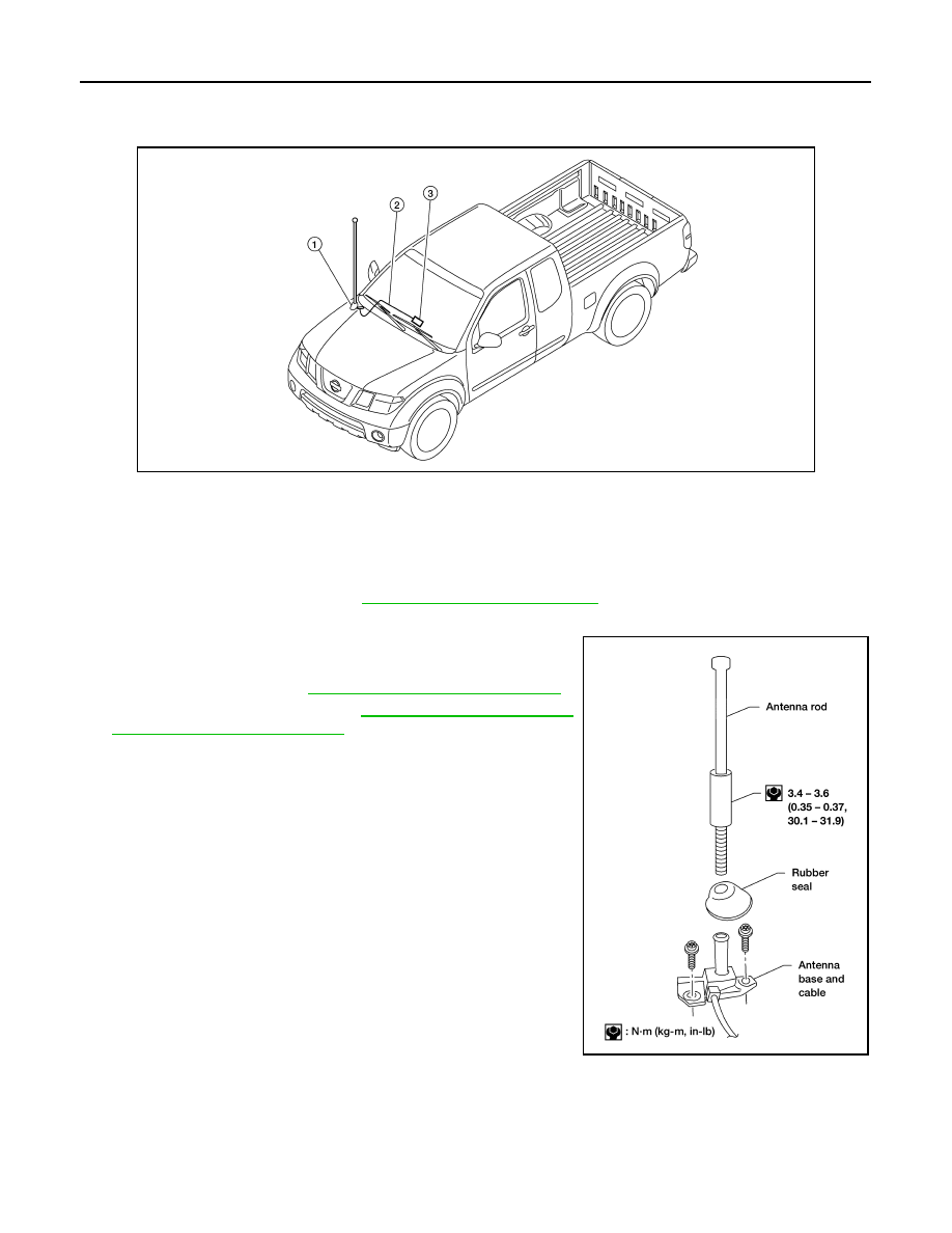
Location of Audio Antenna System Component

INFOID:0000000005274878

Removal and Installation

INFOID:0000000005274879

REMOVAL

1.

Remove lower glove box. Refer to 

IP-11, "Removal and Installation"

.

2.

Disconnect audio antenna cable from antenna feeder.

3.

Remove antenna rod.

4.

Remove rubber seal.

5.

Remove cowl top. Refer to 

EXT-19, "Removal and Installation"

.

6.

Remove fender protector. Refer to 

EXT-22, "Removal and Instal-

lation of Front Fender Protector"

.

7.

Remove antenna base bolts.

8.

Remove antenna base and cable.

INSTALLATION

Installation is in the reverse order of removal.

CAUTION:

Always properly tighten the antenna rod during installation or the antenna rod may bend or break dur-
ing vehicle operation.

AWNIA1798ZZ

1.

Audio antenna

2.

Antenna feeder

3.

Audio unit M43

AEL610C

AV

DIAGNOSIS AND REPAIR WORKFLOW

AV-33

< BASIC INSPECTION >

[PREMIUM AUDIO (KING CAB)]

C

D

E

F

G

H

I

J

K

L

M

B

A

O

P

BASIC INSPECTION

DIAGNOSIS AND REPAIR WORKFLOW

Work Flow

INFOID:0000000005274880

OVERALL SEQUENCE

DETAILED FLOW

1.

GET INFORMATION FOR SYMPTOM

Get detailed information from the customer about the symptom (the condition and the environment when the
incident/malfunction occurred).

>> GO TO 2

2.

CONFIRM THE SYMPTOM

Try to confirm the symptom described by the customer. Verify relation between the symptom and the condition
when the symptom is detected.

>> GO TO 3

3.

DETECT MALFUNCTIONING PART BY DIAGNOSTIC PROCEDURE

Inspect according to Diagnostic Procedure of the system.

ALNIA0182GB

AV-34

< BASIC INSPECTION >

[PREMIUM AUDIO (KING CAB)]

DIAGNOSIS AND REPAIR WORKFLOW

Is malfunctioning part detected?

YES

>> GO TO 4

NO

>> GO TO 2

4.

REPAIR OR REPLACE THE MALFUNCTIONING PART

1.

Repair or replace the malfunctioning part.

2.

Reconnect parts or connectors disconnected during Diagnostic Procedure.

>> GO TO 5

5.

FINAL CHECK

Refer to confirmed symptom in step 2, and make sure that the symptom is not detected.

Was the repair confirmed?

YES

>> Inspection End.

NO

>> GO TO 2

AV

AUDIO SYSTEM

AV-35

< FUNCTION DIAGNOSIS >

[PREMIUM AUDIO (KING CAB)]

C

D

E

F

G

H

I

J

K

L

M

B

A

O

P

FUNCTION DIAGNOSIS

AUDIO SYSTEM

System Diagram

INFOID:0000000005274881

System Description

INFOID:0000000005274882

AUDIO SYSTEM

The audio system consists of the following components
• Audio unit
• Rod antenna
• Steering wheel audio control switches
• Front door speakers
• Front tweeters
• Rear door speakers
When the audio system is on, radio signals are received by the rod antenna. The audio unit then sends audio
signals to the front door speakers, front tweeters and rear door speakers.
Refer to Owner's Manual for audio system operating instructions.

SATELLITE RADIO SYSTEM

The satellite radio system consists of the following components
• Satellite antenna
• Satellite radio tuner
When the satellite radio system is on, radio signals are supplied to the satellite radio tuner from the satellite
antenna. The satellite radio tuner then sends audio signals to the audio unit.
Refer to Owner's Manual for satellite radio system operating instructions.

SPEED SENSITIVE VOLUME SYSTEM

Volume level of this system goes up and down automatically in proportion to the vehicle speed. The control
level can be selected by the customer. Refer to Owner's Manual for operating instructions.

AWNIA1799GB


Content   ..  8  9  10  11   ..