Nissan Terrano model r20 series 2004. Manual - part 372


  Index      Nissan     Nissan Terrano model r20 series 2004 - Service and Repair Manual


Search            


Content   ..  370  371  372  373   ..


Nissan Terrano model r20 series 2004. Manual - part 372


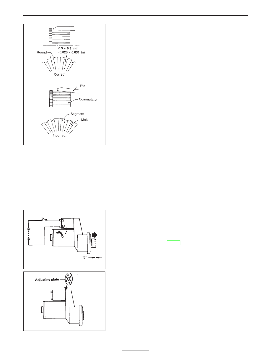
5. Check depth of insulating mold from commutator surface.

I

Less than 0.2 mm (0.008 in) ... Undercut to 0.5 - 0.8 mm
(0.020 - 0.031 in)

Assembly

Carefully observe the following instructions.

GREASE POINT

I

Rear cover metal

I

Gear case metal

I

Center bracket metal

I

Frictional surface of pinion

I

Moving portion of shift lever

I

Plunger of magnetic switch

I

Reduction gear

PINION PROTRUSION LENGTH ADJUSTMENT

Reduction gear type
Compare movement “


” in height of pinion when it is pushed out

with magnetic switch energized and when it is pulled out by hand
until it touches stopper.

Movement “


”:

Refer to SDS (SC-30).

I

Not in the specified value ... Adjust by adjusting plate.

SEL022Z

SEL497D

SEL573B

STARTING SYSTEM

Armature Check (Cont’d)

SC-22

System Description

The alternator provides DC voltage to operate the vehicle’s electrical system and to keep the battery charged.
The voltage output is controlled by the IC regulator.
Power is supplied at all times to alternator terminal 4 (S) (ZD30DDTi engine models) through:

I

10A fuse (No. 31, located in the fuse and fusible link box).

Terminal B supplies power to charge the battery and operate the vehicle’s electrical system. Output voltage
is controlled by the IC regulator at terminal 4 (S) detecting the input voltage (ZD30DDTi engine models). The
charging circuit is protected by the 100A fusible link.
The alternator is grounded to the engine block.
With the ignition switch in the ON or START position, power is supplied

I

through 10A fuse [No. 12, located in the fuse block (J/B)]

I

to combination meter terminal 28 for the charge warning lamp.

Ground is supplied to terminal 2 of the combination meter through terminal 1(L) (TD27Ti engine models) or
3(L) (ZD30DDTi engine models) of the alternator. With power and ground supplied, the charge warning lamp
will illuminate. When the alternator is providing sufficient voltage with the engine running, the ground is opened
and the charge warning lamp will go off.
If the charge warning lamp illuminates with the engine running, a malfunction is indicated.

CHARGING SYSTEM

SC-23

Wiring Diagram — CHARGE —

TD27Ti ENGINE MODELS

YEL055D

CHARGING SYSTEM

SC-24

ZD30DDTi ENGINE MODELS

YEL056D

CHARGING SYSTEM

Wiring Diagram — CHARGE — (Cont’d)

SC-25


Content   ..  370  371  372  373   ..