Nissan Terrano model r20 series 2004. Manual - part 369
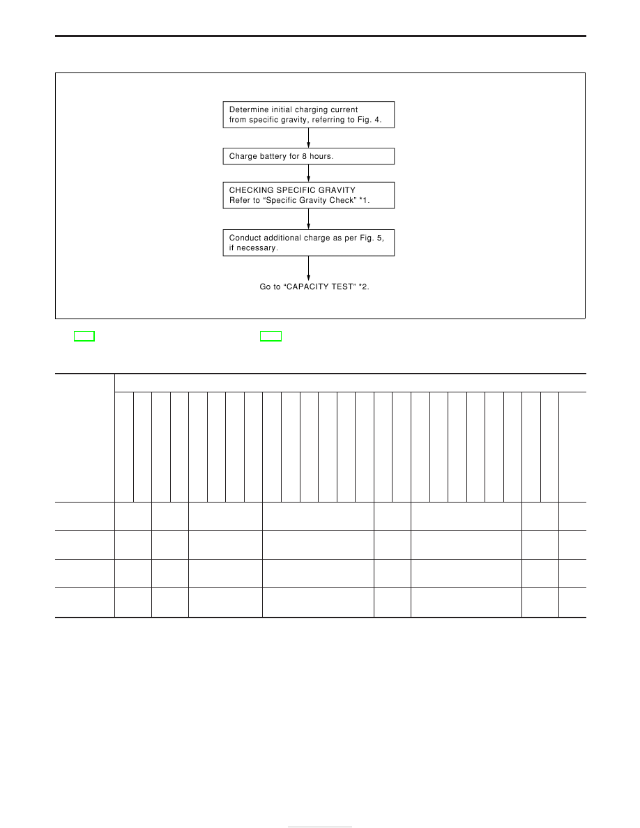
B: STANDARD CHARGE
*1: SC-4
*2: SC-7
Fig. 4 INITIAL CHARGING CURRENT SETTING (Standard charge)
CON-
VERTED
SPECIFIC
GRAVITY
BATTERY TYPE
28B19R(L)
34B19R(L)
46B24R(L)
55B24R(L)
50D23R(L)
55D23R(L)
025
[YUASA
type
code]
027
[YUASA
type
code]
65D26R(L)
L2-580
R/L
(65
Ah)
80D26R(L)
063
[YUASA
type
code]
067
[YUASA
type
code]
096
[YUASA
type
code]
75D31R(L)
L3-760
R/L
(75
Ah)
95D31R(L)
1
15D31R(L)
1
10D26R(L)
95E41R(L)
065
[YUASA
type
code]
075
[YUASA
type
code]
096L
[YUASA
type
code]
010S
[YUASA
type
code]
130E41R(L)
1.100 - 1.130
4.0 (A)
5.0 (A)
6.0 (A)
7.0 (A)
8.0 (A)
9.0 (A)
10.0
(A)
13.0
(A)
1.130 - 1.160
3.0 (A)
4.0 (A)
5.0 (A)
6.0 (A)
7.0 (A)
8.0 (A)
9.0 (A)
11.0
(A)
1.160 - 1.190
2.0 (A)
3.0 (A)
4.0 (A)
5.0 (A)
6.0 (A)
7.0 (A)
8.0 (A)
9.0
(A)
1.190 - 1.220
2.0 (A)
2.0 (A)
3.0 (A)
4.0 (A)
5.0 (A)
5.0 (A)
6.0 (A)
7.0
(A)
I
Check battery type and determine the specified current using the table shown above.
I
After starting charging, adjustment of charging current is not necessary.
SEL758W
BATTERY
Battery Test and Charging Chart (Cont’d)
SC-10