Nissan Terrano model r20 series 2004. Manual - part 302


  Index      Nissan     Nissan Terrano model r20 series 2004 - Service and Repair Manual


Search            


Content   ..  300  301  302  303   ..


Nissan Terrano model r20 series 2004. Manual - part 302


Purpose

The Anti-lock Brake System (ABS) with an integrated Electronic Brake force Distribution (EBD) system con-
sists of electronic and hydraulic components. It allows you to control the braking force so that wheel lock can
be avoided during braking.

The advantages of ABS with EBD
1) Better tracking performance through improved steering wheel control.
2) Improved maneuverability and safer vehicle control.
3) Improved vehicle stability by preventing flat spins.
4) Shorter stopping distance and optimal utilisation of the rear brakes under many different circumstances.

Operation

I

ABS with EBD has self-test capabilities. The ABS warning lamp is illuminated for 1 second each time the
ignition switch is turned “ON”. After the engine is started, the ABS warning lamp turns off. An ABS self-test
is performed the first time the vehicle reaches 6 km/h (4 MPH) to ensure the system is operational. A
mechanical noise may be heard as the ABS performs this self-test and is a normal part of the self-test
feature. If a malfunction is detected during this check, the ABS warning lamp will stay on.
During the self-test, it also performs a EBD check when it detects a failure the ABS warning light will go
on simultaneously with the brake warning light and an audible sound will sound constantly.

I

EBD system will only operate when the ABS is not in active status and it uses the inlet valves of ABS con-
trol unit to limit the pressure to the rear wheels when they tend to go into slip.

I

When the vehicle speed is less than 10 km/h (6 MPH) the ABS system does not operate.

I

While driving, a mechanical noise may be heard during ABS operation, this is a normal system condition.

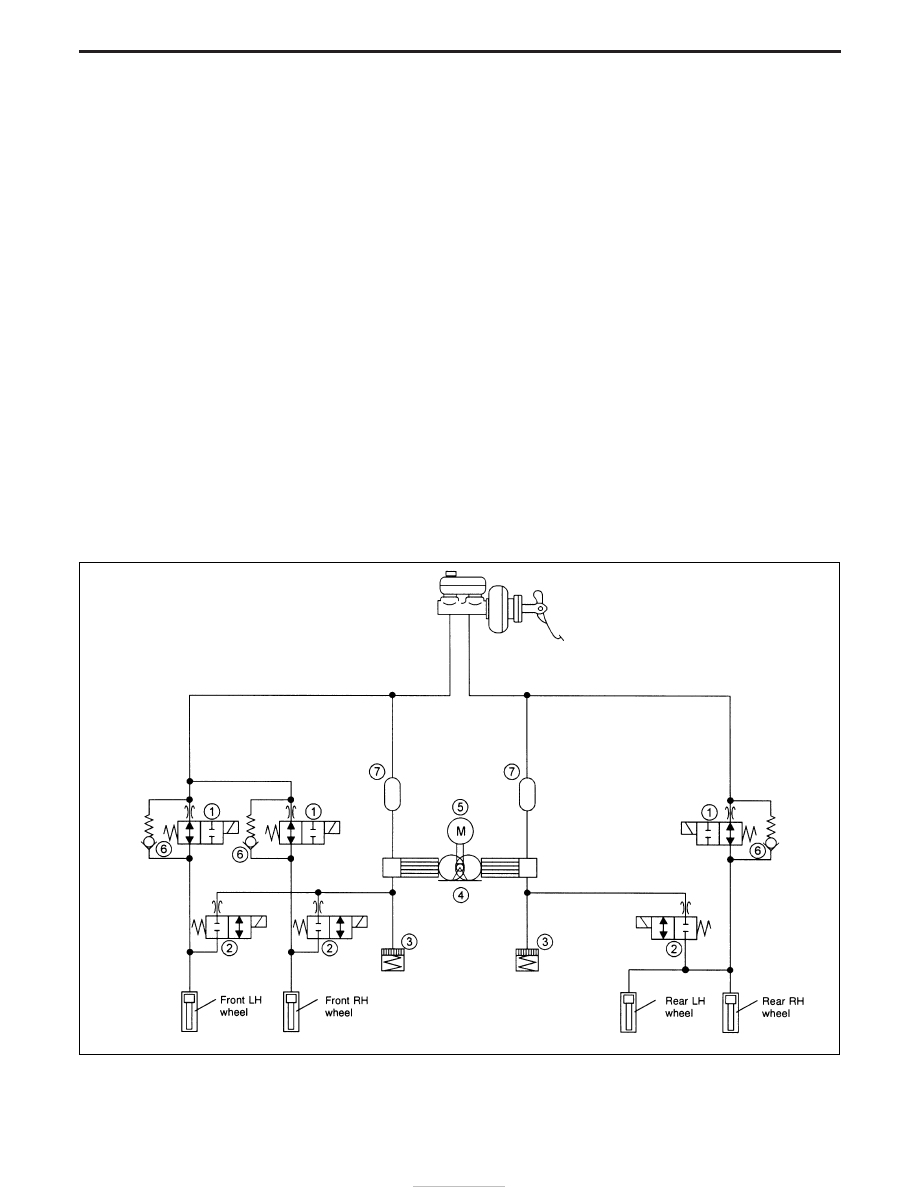
ABS Hydraulic Circuit

q

1

Inlet solenoid valve

q

2

Outlet solenoid valve

q

3

Reservoir

q

4

Pump

q

5

Motor

q

6

By pass check valve

q

7

Damper

NBR346

ANTI-LOCK BRAKE SYSTEM

BR-38

System Description

Sensor

The sensor unit consists of a gear-shaped sensor rotor and a sen-
sor element. The element contains a bar magnet around which a
coil is wound. The sensor is installed on the back of the brake rotor
and the rear brake drum.
As the wheel rotates, the sensor generates a sine-wave pattern.
The frequency and voltage increase(s) as the rotating speed
increases.

Control unit

The control unit computes the wheel rotating speed by the signal
current sent from the sensor. Then it supplies a DC current to the
actuator solenoid valve. It also controls ON-OFF operation of the
valve relay and rotor relay. If any electrical malfunction should be
detected in the ABS or EBD system, the control unit causes the
warning lamp(s) to light up, combined with an audible sound.
In this condition, the ABS or EBD will be deactivated by the control
unit, and the vehicle’s brake system reverts to normal operation.
(Fail-safe mode)

YBR262

SBR124B

YBR263

ANTI-LOCK BRAKE SYSTEM

BR-39

G SENSOR

The G sensor analyses deceleration during braking to determine whether the vehicle is being driven on a road
with low surface resistance (µ) (snow-covered road, etc.). The ABS control unit uses the signal from the
deceleration sensor to compensate for road surface conditions when controlling the braking operation.

NBR136

ANTI-LOCK BRAKE SYSTEM

System Description (Cont’d)

BR-40

ACTUATOR AND ELECTRIC UNIT

The actuator and electric unit contains:

I

An electric motor and pump

I

Two relays

I

Six solenoid valves, each inlet and outlet for
— LH front
— RH front
— Rear

I

ABS control unit

These components control the hydraulic circuit. The ABS control
unit directs the actuator to increase, hold or decrease hydraulic
pressure to all or individual wheels. The ABS actuator and electric
unit cannot be disassembled and has to be serviced as an assem-
bly.

YBR299

ANTI-LOCK BRAKE SYSTEM

System Description (Cont’d)

BR-41


Content   ..  300  301  302  303   ..