Nissan Terrano model r20 series 2004. Manual - part 270
 

  Index      Nissan     Nissan Terrano model r20 series 2004 - Service and Repair Manual


Search            


Content   ..  268  269  270  271   ..


Nissan Terrano model r20 series 2004. Manual - part 270


13. Measure both bearing in the same way and write the left side

bearing measurement next to “E” and the right side bearing
measurement next to “F”.

14. Substitute these values into the equation to calculate the thick-

ness of the shim.

If values signifying A, B, C, D, G

1

and G

2

are not given, regard

them as zero and calculate.

Left side:

T

1

= (A + C + G

1

− D) x 0.01 + 0.76 − E

Right side:

T

2

= (B + D + G

2

) x 0.01 + 0.76 − F

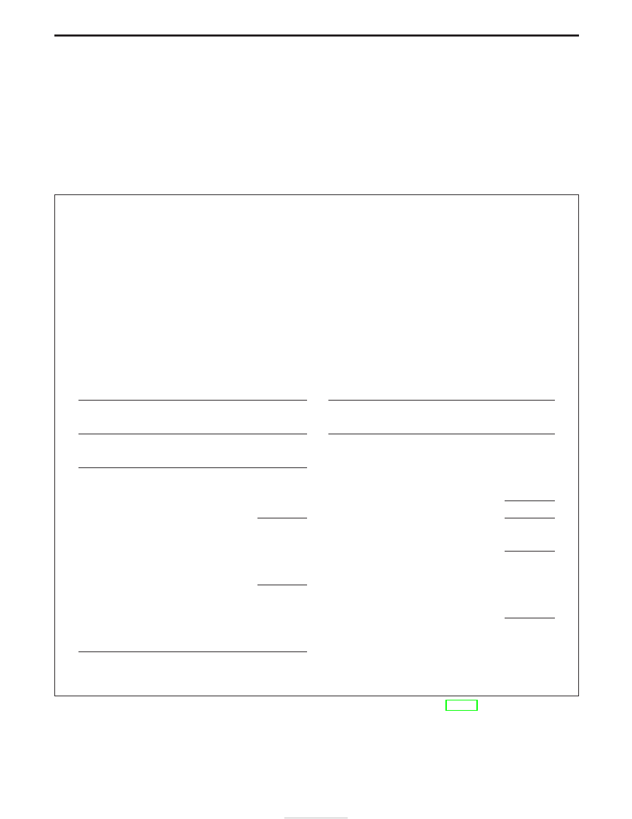
Example

A = 5

E = 0.11

B = 5

F = 0.15

C = 3

G

1

= 4

D = 3

G

2

= 1

Left side:

Right side:

T

1

= (A + C + G

1

− D) x 0.01 + 0.76 − E

= (5 + 3 + 4 − 3) x 0.01 + 0.76 − 0.11

T

2

= (B + D + G

2

) x 0.01 + 0.76 − F

= (5 + 3 + 1) x 0.01 + 0.76 − 0.15

(1)

A ........................................................5

(1)

B .......................................................5

+ C.....................................................+3

+ D....................................................+3

8

8

+ G

1

...................................................+4

+ G

2

..................................................+1

12

9

− D.....................................................−3

9

(2)

9

(2)

9

x0.01

x0.01

0.09

0.09

(3)

0.09

+0.76

(3)

0.09

0.85

+0.76

0.85

(4)

0.85

−0.15

(4)

0.85

0.70

− E

−0.11

0.74

T

2

= 0.70 mm

T

1

= 0.74 mm

15. Select the proper shims. (Refer to PD-57.)
If you cannot find the desired thickness of shims, use shims
with the total thickness closest to the calculated value.

ADJUSTMENT (R180A)

Side Bearing Preload (Cont’d)

PD-26

Tooth Contact

Gear tooth contact pattern check is necessary to verify correct
relationship between ring gear and drive pinion.
Hypoid gear sets which are not positioned properly in relation to
one another may be noisy, or have short life span or both. With a
pattern check, the most desirable contact for low noise level and
long life can be assured.

1. Thoroughly clean ring gear and drive pinion teeth.
2. Sparingly apply a mixture of powdered ferric oxide and oil or

equivalent to 3 or 4 teeth of ring gear drive side.

3. Hold companion flange steady by hand and rotate the ring gear

in both directions.

SPD357

SPD653

NPD003

ADJUSTMENT (R180A)

PD-27

Extension Tube and Differential Side Shaft

1. Measure rear axle bearing end play.

Rear axle bearing end play (A − B):

0.1 mm (0.0039 in) or less

The end play can be adjusted with bearing adjusting shim.
(Refer to PD-57.)

2. Install oil seal.

3. Install the spacer, grease seal, extension tube retainer, adjust-

ing shim, shim and shim collar onto the differential side shaft.

4. Install differential side shaft assembly into extension tube.

SPD699

SPD654

SPD655

ASSEMBLY (R180A)

PD-28

Differential Case

1. Measure clearance between side gear thrust washer and dif-

ferential case.

Clearance between side gear thrust washer and differ-
ential case (A − B):

0.10 - 0.20 mm (0.0039 - 0.0079 in)

The clearance can be adjusted with side gear thrust washer.
(Refer to PD-57.)

2. Apply gear oil to gear tooth surfaces and thrust surfaces and

check to see the turn properly.

3. Install L.H. and R.H. differential cases.

4. Place differential case on ring gear.
5. Apply locking agent [Locktite (stud lock) or equivalent] to ring

gear bolts, and install them.

Tighten bolts in a criss-cross fashion, lightly tapping bolt head
with a hammer.

6. Press-fit side bearing inner cones on differential case with Tool.

Tool number:

q

A

ST33230000

q

B

ST33061000

SPD656

SPD643

SPD746

PD353

ASSEMBLY (R180A)

PD-29


Content   ..  268  269  270  271   ..